sweetchoto
Full Member level 2
Dear All,
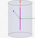
Kindly see the attached HFSS file,it contains two separate Designs. One is of 'single Half-wavelength Dipole' operating at 2.4 GHz. This design is perfectly fine and giving the results as expected. The other second design consist of 3 Identical Dipoles(operating at 2.4 GHz), The Dipole at centre is acting as Receiver(Rx) whereas the Dipoles at each end are acting as Trasmitters(Tx). One Transmitter(Dipole) is placed at distance 'D(any distance)' from Receiver(Rx) and Second Transmitter(Dipole) is placed at a distance 'D+Lamda/2' where Lamda is calculated using 2.4 GHz. Then, the effect of these two transmitters on Receiver antenna is plotted by using the simple equation of
Coupling= (S(1,2)+S(1,3)) dB
Here 2,3 denotes the transmitter dipoles and 1 denotes the receiver dipole in centre and i gave it the name Coupling.
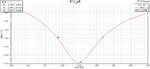
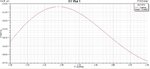
In principle, what i should get is a Null at 2.4 GHz at receiver antenna location due to the cancellation of transmitting signals of the two transmitter dipoles since they are placed at such distances from receiver antenna that their signals will reach at the receiver out of phase and cancel each other out. But in my simulation result,i get the opposite of it. Instead of getting a Null at 2.4 GHz i get a peak. Kindly see the attached file what i have done and if someone could give me any idea as what to do or what i am doing wrong. I will be thankful to him.
Looking forward to hear some sensible comments.
/SC
Kindly see the attached HFSS file,it contains two separate Designs. One is of 'single Half-wavelength Dipole' operating at 2.4 GHz. This design is perfectly fine and giving the results as expected. The other second design consist of 3 Identical Dipoles(operating at 2.4 GHz), The Dipole at centre is acting as Receiver(Rx) whereas the Dipoles at each end are acting as Trasmitters(Tx). One Transmitter(Dipole) is placed at distance 'D(any distance)' from Receiver(Rx) and Second Transmitter(Dipole) is placed at a distance 'D+Lamda/2' where Lamda is calculated using 2.4 GHz. Then, the effect of these two transmitters on Receiver antenna is plotted by using the simple equation of
Coupling= (S(1,2)+S(1,3)) dB
Here 2,3 denotes the transmitter dipoles and 1 denotes the receiver dipole in centre and i gave it the name Coupling.
In principle, what i should get is a Null at 2.4 GHz at receiver antenna location due to the cancellation of transmitting signals of the two transmitter dipoles since they are placed at such distances from receiver antenna that their signals will reach at the receiver out of phase and cancel each other out. But in my simulation result,i get the opposite of it. Instead of getting a Null at 2.4 GHz i get a peak. Kindly see the attached file what i have done and if someone could give me any idea as what to do or what i am doing wrong. I will be thankful to him.
Looking forward to hear some sensible comments.
/SC
")