Gaber Mohamed Boraey
Full Member level 2
Hello everyone
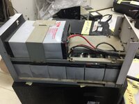
We have powrcom 3kva ups, with problem of charging issue
The batteries are 4 in series and parallel with another 4 , so total voltage is 48v
I’ve attached the service manual, please look at smk3000 model, Qun807 circuit
Look at page 35, this page for complete circuit

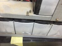
The charging voltage not stable, and the ups came with bad batteries , look like damaged , size became big as attached
Can you guide me which circuit is the charging circuit?
We have powrcom 3kva ups, with problem of charging issue
The batteries are 4 in series and parallel with another 4 , so total voltage is 48v
I’ve attached the service manual, please look at smk3000 model, Qun807 circuit
Look at page 35, this page for complete circuit
The charging voltage not stable, and the ups came with bad batteries , look like damaged , size became big as attached
Can you guide me which circuit is the charging circuit?