Welcome to our site! EDAboard.com is an international Electronics Discussion Forum focused on EDA software, circuits, schematics, books, theory, papers, asic, pld, 8051, DSP, Network, RF, Analog Design, PCB, Service Manuals... and a whole lot more! To participate you need to register. Registration is free. Click here to register now.
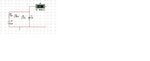
Hi Friends this is my circuit in that i give the all resistor value i want to know how to calculated this voltage output if the resistor value Rx changes please give me the formula for calculate voltage output for this circuit
If the input is a simple dc source and it has been on for a "long time", then you are in dc steady state; therefore, the capacitor may be replaced by and open circuit. The voltage measured by U1 can be written down by inspection using voltage division
\[
U_1 = \frac{R_x||R_2}{R_1 + (R_x||R_2)} V_1
\]
where \[R_x||R_2\] is the parallel combination of \[R_x\] and \[R_2\]. For the values given \[R_x||R_2 \approx 9.09 \Omega\]. The numerical value of the voltage measured by the voltmeter is
\[
U_1 = \frac{9.09 \Omega}{1\text{k}\Omega + 9.09 \Omega} 12 \text{V} \approx 108.1 \text{mV}
\]
And it looks like this is exactly what is shown in your picture (0.108).
This site uses cookies to help personalise content, tailor your experience and to keep you logged in if you register.
By continuing to use this site, you are consenting to our use of cookies.