Continue to Site

Welcome to EDAboard.com

Welcome to our site! EDAboard.com is an international Electronics Discussion Forum focused on EDA software, circuits, schematics, books, theory, papers, asic, pld, 8051, DSP, Network, RF, Analog Design, PCB, Service Manuals... and a whole lot more! To participate you need to register. Registration is free. Click here to register now.

[SOLVED] [MOVED] Digital Project Help

Status
Not open for further replies.

Gentem

Junior Member level 1
Joined
Apr 10, 2017
Messages
16
Helped
0
Reputation
0
Reaction score
0
Trophy points
1
Activity points
140
Hi,

I have been a set a project to complete by the end of the month, I do not know much about sequential logic circuits or any other aspects that are mentioned in the brief, so that leaves me in an awkward position as I do not know how to even begin. :-( The only things I have learnt so far is some basics on flip-flops and timing diagrams, other than that, please help...

The brief:

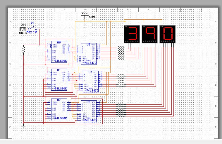
You are required to design and build a circuit to display the frequency of a TTL compatible square wave. Frequency meters consist of a counter, a display and a gate that is opened and closed under the control of an accurate oscillator, plus some control. Your circuit should consist of three seven segment displays and indicate the frequency in the range 0 – 999 Hz. Your circuit should freeze the display when the gate closes so that it can be read, and reset it to zero before the gate opens again. It will therefore be necessary to design some gate and reset control circuitry, and possibly a latch.

Thank you for taking the time to read this, I hope someone can help.

Gentem
 

I've moved this to the "Elementary Electronic Questions" where you will get more exposure.

This is a fairly simple project but before going into detail, what technology do you want to use? From the decription and nature of the task I would guess you are supposed to design and build it using TTL (74 series) or basic CMOS logic gates. There are single IC solutions but that would defeat the design challenge.

The brief tells you almost everything you need to know. Break it down into individual steps and you will see it is quite straightforward. Remember a frequency counter is nothing more than an 'up' counter that operates within a set time period. For example, if you set the period to 1 second, it would count cycles per second, in other words in Hz which is actually what you want!

Brian.
 
  • Like
Reactions: Gentem

    Gentem

    Points: 2
    Helpful Answer Positive Rating
I've moved this to the "Elementary Electronic Questions" where you will get more exposure.

This is a fairly simple project but before going into detail, what technology do you want to use? From the decription and nature of the task I would guess you are supposed to design and build it using TTL (74 series) or basic CMOS logic gates. There are single IC solutions but that would defeat the design challenge.

Brian.

Yes, it's with the 74 series chips.

This is what I have understood from the brief and from what you have suggested so far,

17902632_10212858798847767_376888885_o.jpg
 

(sorry for wrong order of the posts)
Hi,

Homework.
In my eyes it makes sense to spend a little effort on your own.

Decide how to begin.
Draw a sketch of the complete task. Show us your drawing.
Divide the task in several smaller tasks.
Try to solve each single task and show us your results.

***
Btw.: The professionals have to do the same...

Klaus


- - - Updated - - -

Hi,

so far so good.

Now you need a timing diagram. At least for GATE, RESET, LATCH_ENA.

Klaus
 
  • Like
Reactions: Gentem

    Gentem

    Points: 2
    Helpful Answer Positive Rating
... and if you want to display 0-999 you need three counter stages (BCD counters will be easiest to use), three latches and three displays. The overflow from the units counter goes to the tens counter and the tens overflows to the hundreds counter but all the latches are clocked in parallel so they 'freeze' all the digits simultaneously.

Brian.
 
  • Like
Reactions: Gentem

    Gentem

    Points: 2
    Helpful Answer Positive Rating
I think I understand the theory behind the counter, after having a look at the JK flip flop and then using the 74LS90 to try and get a single output which in turn if I understand correctly, that the output of one would be the input to another 74LS90 for as many digits that were required, in my case 3 74LS90's.

Below is what I have attempted to simulate,

17887576_10212861175387179_950698254_o.png

It doesn't work and at the moment I am struggling to comprehend how all the sub circuits should look or work together :bang:
 

Pin 10 of 7490 should go to ground.

- - - Updated - - -

Pin 5 of 7490 should go to V+.

- - - Updated - - -

Perhaps the simulation creates power connections invisibly? If so, then disregard my message.
 
  • Like
Reactions: Gentem

    Gentem

    Points: 2
    Helpful Answer Positive Rating
The LT (Lamp Test) pin on the 74LS47 should be high too. When grounded it turns all segment outputs on.

Note that in the real World, you need a resistor is series with each segment pin on all the displays to limit the LED current. The simulaton should show it working normally but in practice, without the resistors either the display, the 74LS47 or both will be damaged.

Brian.
 
  • Like
Reactions: Gentem

    Gentem

    Points: 2
    Helpful Answer Positive Rating
I've finally managed to get the basic counter to work and have now made it so that it counts up and overflows to the next counter with the activation of a switch. now I just need to understand how to do with an automatic clock pulse which pauses and

counters.png

A "Bit" of a mess, but definitely making progress!

Now I just need to understand how to have a clock pulse input and a frequency counter that outputs to the displays... :thinker:
 

Ok, I've cleared it up now, it counts fine with a clock input and I've included a switch so I can stop the counter counting up...

I can't figure out how to go from here...


Well done!

You don't need a clock pulse as such but you do need a precise timing mechanism to produce the sampling window.

The sequence of events you have to generate is:
1. clear the counters (hint: disconnect one of the R0 pins from ground, link them together and use as a common reset line)
2. open the 'gate' to allow your input signal to reach the first counter
3. wait for the sampling time (window) to finish (say 1 second from the timer circuit)
4. close the gate so no more cycles are counted
5. wait a while so the display appears stable
6. repeat from step 1.

Note that using the design you have shown has a drawback which you probably haven't noticed, it shows the count 'live'. While triggering it manually can't see the numbers actually change but in a frequency counter the number is changing throughout the gate period. For example, if you count for 1 second, during that time the numbers will be changing and you will see a blur of segments turning on and off. The way to overcome this is to add an extra stage between the counter (LS90) and the display driver (LS47). If you add a 4-bit latch (74LS75 for example) you can snapshot the counter output and freeze the count value while the counter itself resets and does the next count, that makes the display stay constant between each measurement.

Brian.
 
  • Like
Reactions: Gentem

    Gentem

    Points: 2
    Helpful Answer Positive Rating
Ok, I've succeeded in making a reset switch for all counters, and I've attempted to add the latches, and I've also wired up the frequency meter to the input gate to see what's happening, and as you said, the frequency changes very rapidly when the switch is opened and closed. Although the input part of the circuit is behaving as it should, the frequency is not being delivered to the displays.

I have checked the wiring according to a 74LS75 datasheet and I believe the connections are correct...

Any Ideas? :roll:

17916155_10212873482734855_996771333_o.png17902929_10212873474614652_800425429_o.png

Thanks in advance,

Gentem
 

You are getting there.

The problem is the 'LE' spins on the latches. When the LE (clock) pin is high, the latch is transparent. That means whatever goes in on the 'D' pin comes out on the corresponding 'Q' pin (and it's inverse on -Q). When LE is low, whatever was on the Q pin is frozen stays there, even if it's D input is still changing. If you connect all the LE pins together and try driving them high or low you will see how it works. The intention is to hold the digits on the display until they are ready to be updated, even though the next count is being prepared at the time. It gives you the final result of the count, frozen while the next count is in progress, rather than seeing the count in progress.

What you need to do is add an action to the controlling sequence so that after the gate period has ended, but before the counter is reset, you drive the LE pins high and then low again so the count is updated and held in the latch.

Your design is almost completed. All you need to do now is draw a timng chart of the different actions. You will see some of the signals you need are simply a pulse starting from the edge of one of the other signals so it isn't as hard as it sounds. From the chart you will be able to work out the sequence of control signals you need. Have a go and post the timing diagram for comments.

Brian.
 
  • Like
Reactions: Gentem

    Gentem

    Points: 2
    Helpful Answer Positive Rating
Hi again,

I have a switch now that connects the LE pins together, and when I open it, whatever is on the counter is frozen, and it does exactly what you said, it would update the counter if the LE switch is switched on and off even if the input switch is off...

I am struggling to understand the rest of it, and also I have no clue as to how the timing diagrams are supposed to look, I can't comprehend how it's supposed to look or how to draw them..

Also the counters unlike before, where it would at least count up, now count up to something like this when the input switch is closed:

000
048
080
000

I'm confused as to where it is getting these numbers from when the input frequency is 500Hz.
At the input gate, I've checked the frequency counter when the switch is opened and closed rapidly, that the frequency changes 0-500hz, but these aren't reflected in the counters.

This is what the circuit looks like now:

17916159_10212880137301215_1912372806_o.png

Sorry again for the questions, and thank you in advance! I really appreciate the support!

Gentem
 

I suspect the reason you see different numbers is the gate period isn't set yet. At the moment, you have a pulse counter that just keeps increasing until it overflows or you reset it, what you actually need is a counter that starts from zero and then counts for a specific period before stopping and being read. For example, if you are applying 123 Hz, at the moment the counter increases 123 times per second but after 2 seconds it will reach 246 and after 3 seconds 369 and so on. To make it read 123 you have to 'gate' the input signal so only one seconds worth of pulses reach the counter.

The next step is to add a logic gate before pin 14 of U5 so you can turn the flow of pulses on and off. The other input to the gate is the precisely timed 'gate period' which you have to generate from a stable reference oscillator. Typically this will be a quartz crystal oscillator at say 10MHz which is followed by a chain of 'divide by 10' counters, similar to the counters you already have. By selecting the output from each divider you get (assuming 10MHz) 1MHz, 100KHz, 10KHz, 1KHz, 100Hz, 10Hz and 1Hz square waves which you can use as the gate signal. The higher the frequency, the shorter the gate period will be so theoretically you can measure higher frequencies in the same number of digits. Example: with 1 second gate you can measure 1Hz to 999Hz in three digits, if you selected 1ms (1KHz) it would measure 1Khz to 999KHz and with 1us (1MHz) it would count 1MHz to 999MHz although in practice the logic gates wouldn't be able to work beyond about 30MHz. This is exactly how the range switch works on a frequency counter, it just selects how long the gating period will be.

Brian.
 
  • Like
Reactions: Gentem

    Gentem

    Points: 2
    Helpful Answer Positive Rating
I understand what needs to be done, but I've run into another issue, I've been spending all day trying to figure out how to create this divider circuit. Multisim does not seem to have a 10Mhz crystal oscillator, so the next best thing from what I've researched is a 32.768KHz oscillator, but every schematic I've found for that oscillator circuit requires IC's that are also missing from Multisim...

I feel like I am missing something very obvious...

17887662_10212882416038182_2109446144_o.jpg

- - - Updated - - -

Never mind, I found them the components! :oops:
 

I've never used multisim before, but this seems to indicate there is a clock source component.
See section 1.8 on page 1-5
 
  • Like
Reactions: Gentem

    Gentem

    Points: 2
    Helpful Answer Positive Rating
Ok, so I've had a look and decided to go with the 32.768Khz to 1Hz method, and have found a schematic online to follow to generate 1Hz, unfortunately, nothing works now and I'm not receiving any signal from the frequency counter when attached to the inputs.

I hope I've done everything right, as I have been double checking along the way... Very confused.

I can't seem to attach a multisim file, so I've saved it as a pdf file.

View attachment FrequencyCounterProjectv1.pdf


Help is greatly appreciated! Thank you

Gentem
 

What you should see is the count freezing for half a second then counting for half a second as the signal from the 4013 goes up and down. I do not have Multisim but it could be that it doesn't allows mixed CMOS and TTL circuits to connect.

What does the simulator say is on the frequency counter (output of the 4013) ?

Brian.
 
  • Like
Reactions: Gentem

    Gentem

    Points: 2
    Helpful Answer Positive Rating
Status
Not open for further replies.

Part and Inventory Search

Welcome to EDABoard.com

Sponsor

Back
Top