Continue to Site

Welcome to EDAboard.com

Welcome to our site! EDAboard.com is an international Electronics Discussion Forum focused on EDA software, circuits, schematics, books, theory, papers, asic, pld, 8051, DSP, Network, RF, Analog Design, PCB, Service Manuals... and a whole lot more! To participate you need to register. Registration is free. Click here to register now.

MOSFET Power dissipation in DC-DC forward converter

Status
Not open for further replies.

electronZ

Member level 2
Joined
Apr 11, 2010
Messages
43
Helped
0
Reputation
0
Reaction score
0
Trophy points
1,286
Activity points
1,602
Dear all

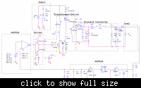
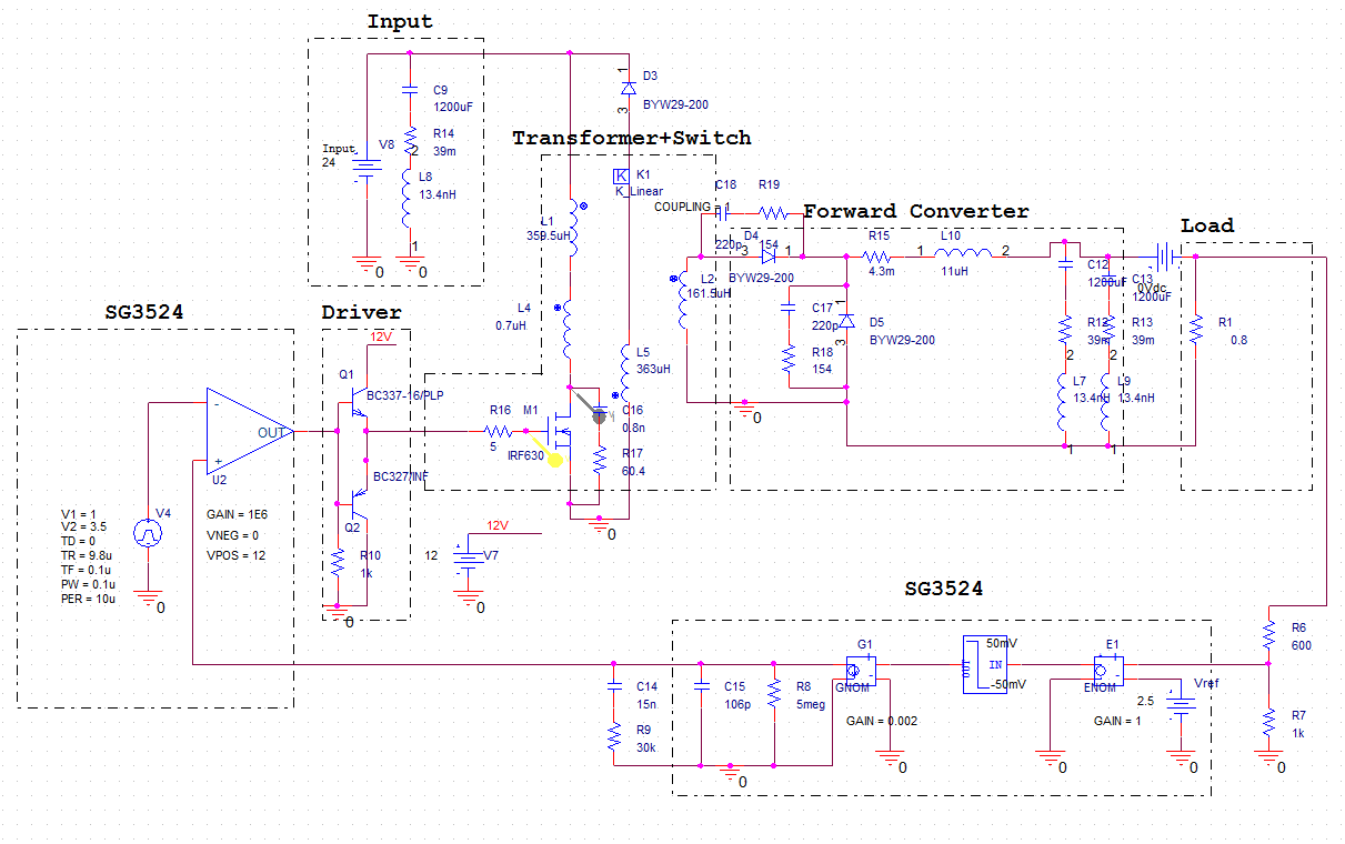
Here is the schematic


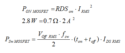
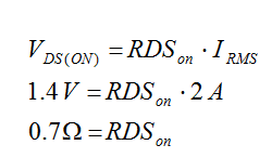
The formulars am using:
35_1293660448.png


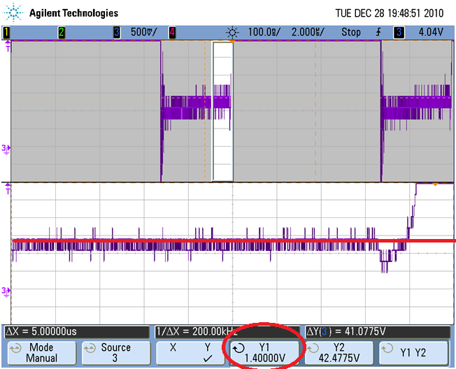
1. Is it right to use Vrms and Irms?
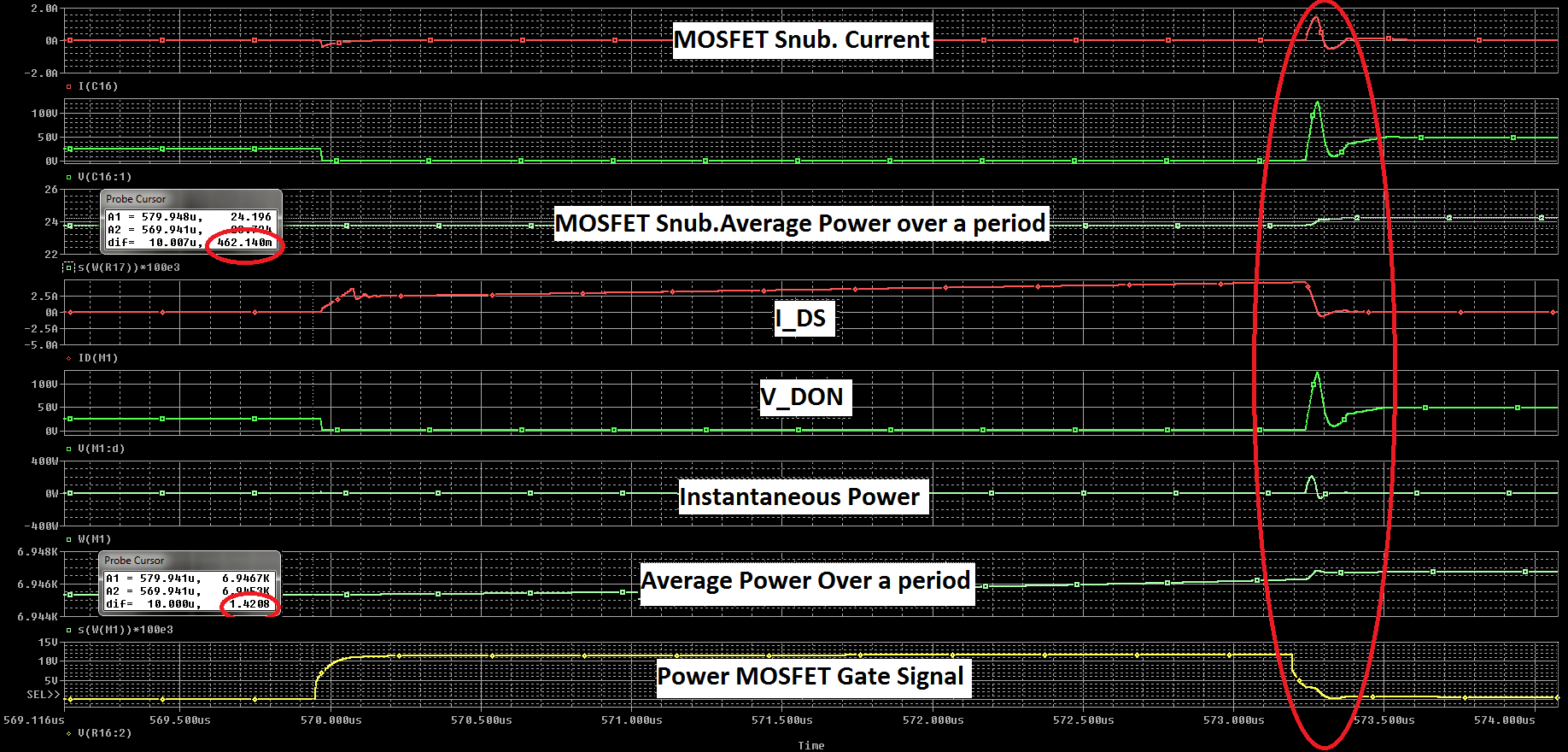
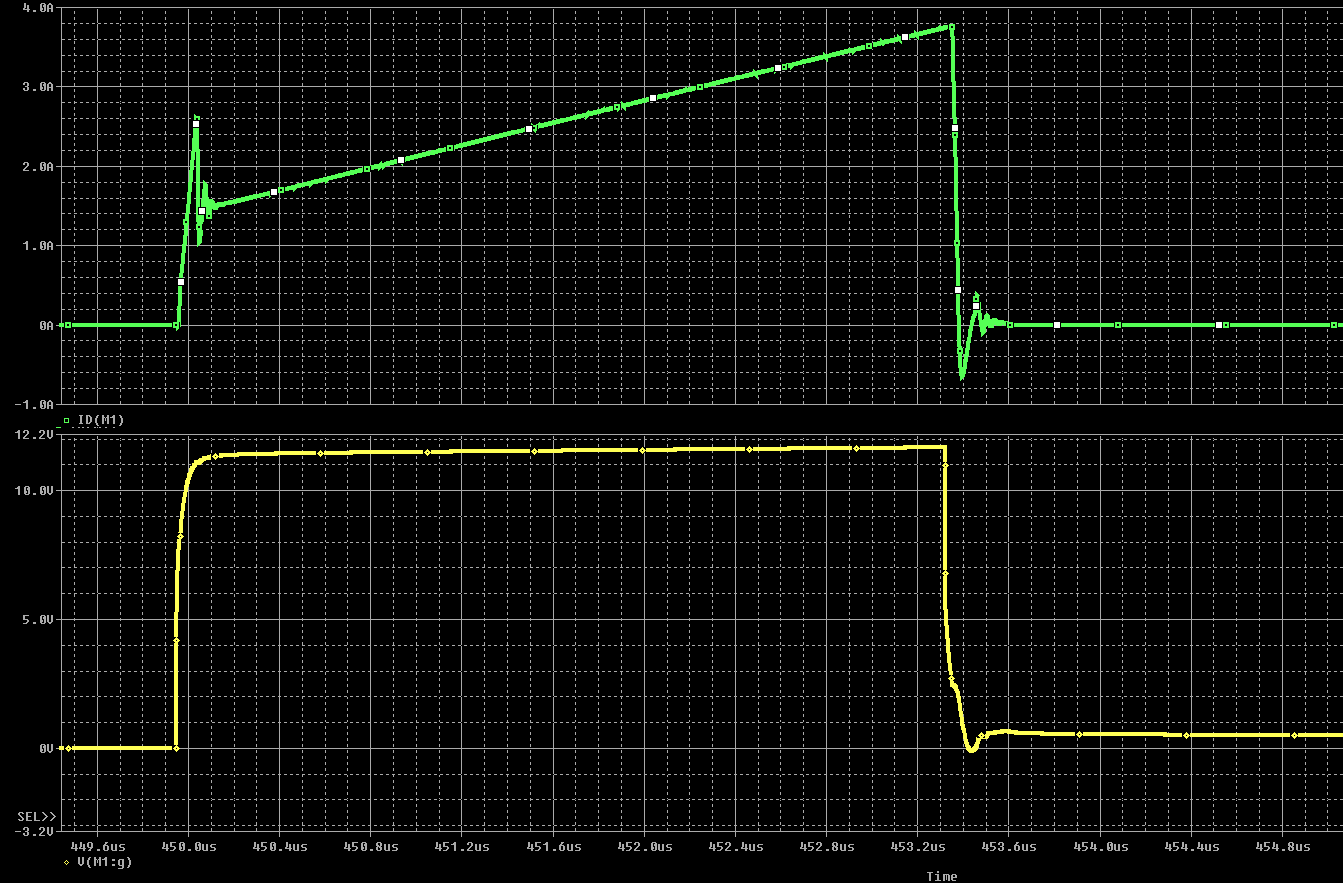
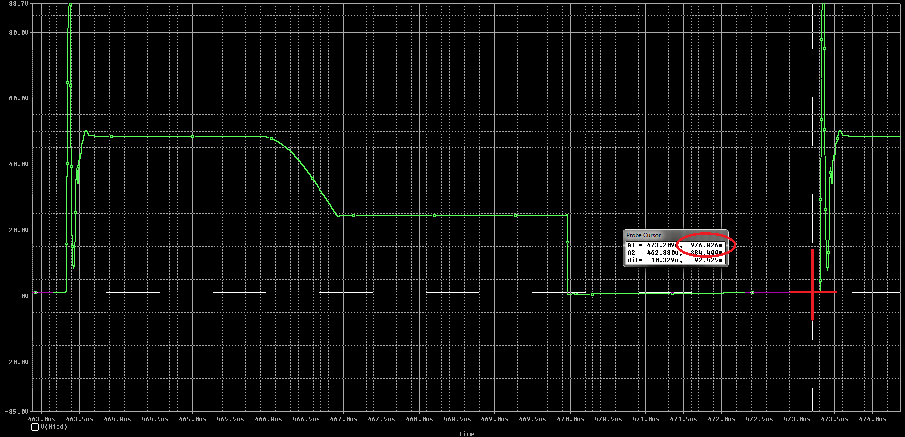
2.The rise and fall time values, extracted from simulations, are around 5 times bigger than datasheets (IRF630). See simulation ss

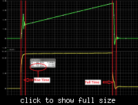
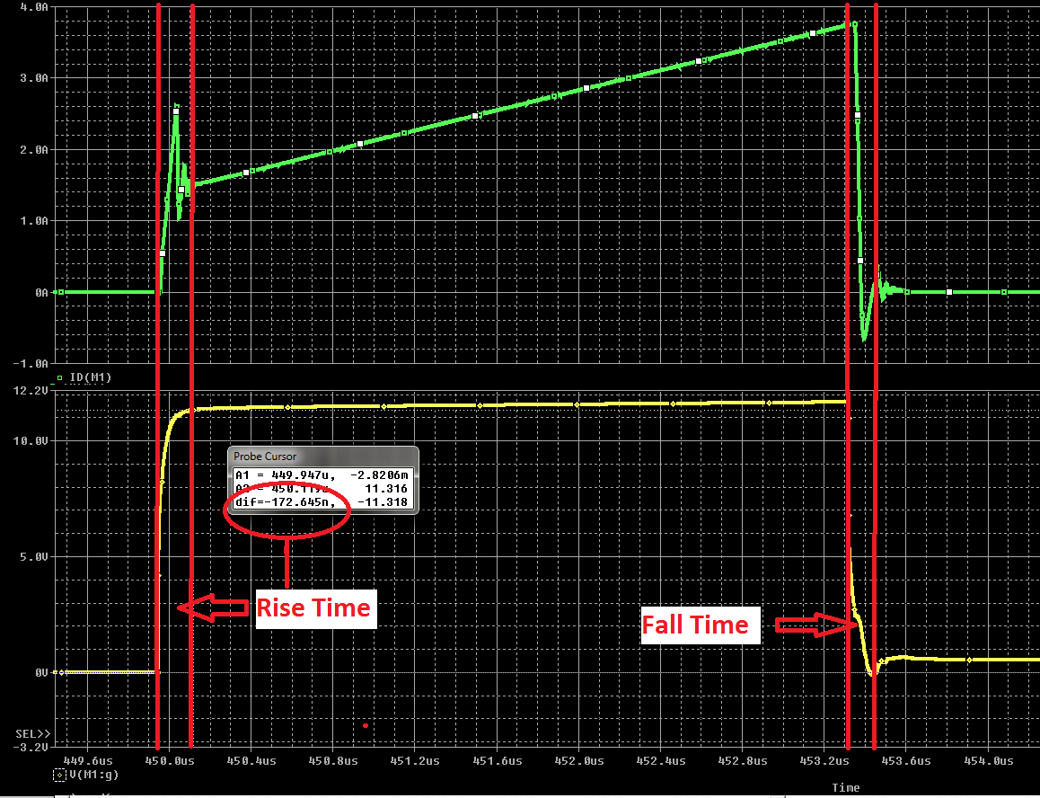
In the simulations you see Ids on top and Vgate in the bottom.

This gives me Psw around 0.9 W!
That gives me total power dissipation of 3.7W ?! -a lot isnt?

Can this be correct?

Thanks
 

Although a 200V FET won't be first choice for the design, Rdson of IRF630 isn't 0.7 ohm. Also ton and toff aren't correctly extracted from the waveforms. It's easy to make the simulator display the instantaneous power Vds*Id and calculate the switching losses exactly, it's simply ∫Vds*Id dt.
 

Rdson of IRF630 isn't 0.7 ohm.
That value was found by measuring the voltage during ON period.

I used Ohm's law to find RDSon
98_1293664137.png

-Is that wrong?

Also ton and toff aren't correctly extracted from the waveforms.
Can you highlight how to read them, please?
 

That value was found by measuring the voltage during ON period.
The datasheet specifies 0.3 ohm maximum. I don't know what's wrong, may be it's an incorrect probe adjustment.
Can you highlight how to read them, please?
The shown waveform is different from the text book model for switching power losses. You should refer to a literature, where the formula is derived. Then figure out, how to apply the model to the shown waveform. Or, as suggested, visualize the actual losses in the simulation and compare with the theoretical value.
 
Hi,
Although very small, there is also a gate charge loss.
Pgate = Qg * Vgs * f

According to ST Microelectronics AN2794, Conduction loss, Pcond = 1.6 * Rdson * (IMOSRms^2)

The Intersil IRF630 datasheet states a typical RDSon of 0.25ohms and max of 0.4ohms, so when you get 0.7ohms, there must be a mistake somewhere.

Hope this helps.
Tahmid.
 
Hi

Thank you for taking the time to answer.

The high VD ON is also present in the simulation results.


That was not what I asked in the first place, but ok.. let me try to brain storm a bit :)
 

The high VD ON is also present in the simulation results.
I see about 1 V. But according to your previous simulation waveform Id is 3.8 A, so Rds would be below 0.3 Ohm.
 

I see about 1 V. But according to your previous simulation waveform Id is 3.8 A, so Rds would be below 0.3 Ohm.
Afaik, it is the Irms that is used, and not peak? :/
 

I prefer ohms law to calculate the relation of Vds, Ids and Rds. You showed an instantaneous Vds (at end of conduction period) of 1 V, Ids is 3.8 A, so how about Rds?
 

I prefer ohms law to calculate the relation of Vds, Ids and Rds. You showed an instantaneous Vds (at end of conduction period) of 1 V, Ids is 3.8 A, so how about Rds?
Thats what I actually asked you in #3, if it is wrong or right to use Ids_RMS. As you can see am using Ids_RMS (Measured value, almost the same as simulated). I guess it is wrong then?

Lets say it is 0.3 Ohm. If I want to calculate the power loss during On period, should I use Irms? I want the average power, correct?

Thank you FvM
 

Calculation of losses is a different thing. The formulas in your original post are basically correct. Tahmid has quoted an additional factor of 1.6, by I don't see, where it comes from.

Rds*Ids² is valid for resistors in general. Irms must be determined however, it's always higher than the average value Iav, the factor depends on both, duty cycle and current ripple.

P.S.: Instead of calculating conduction and switching losses separately, you can also average the instantaneous power Ids*Vds over one period and get the total Id related losses.
 
Last edited:
P.S.: Instead of calculating conduction and switching losses separately, you can also average the instantaneous power Ids*Vds over one period and get the total Id related losses.
Thanks, I will do that
 

I agree with FvM, Ids*Vds over one period is the total losses including conduction and switching losses. You don't need to calculate them separately. You will need to calculate them only if you need to know which one of them is higher (conduction or switching) to reduce at and achieve high efficiency.

Hope this help. Best wishes
 

Tahmid has quoted an additional factor of 1.6, by I don't see, where it comes from.

It is stated in ST Microelectronics AN2794 page 17, equation 62. Pcond = 1.6 * Rdson * (IMOSRMS)^2. Here RMS current is taken, not peak.

Hope this helps.
Tahmid.
 
Last edited:

Hope this helps
Actually not. I have read the AN before posting my comment. As mentioned below, P = R*Irms² is valid for resistors in general. I guess, the authors of the said application note had an idea why adding a factor of 1.6 in this place. But it's not obvious, and surely not valid in general. If you understood where the factor comes from, please clarify.


Switching loss's marked with red circle.
 

Status
Not open for further replies.

Similar threads

Part and Inventory Search

Welcome to EDABoard.com

Sponsor

Back
Top