Continue to Site

Welcome to EDAboard.com

Welcome to our site! EDAboard.com is an international Electronics Discussion Forum focused on EDA software, circuits, schematics, books, theory, papers, asic, pld, 8051, DSP, Network, RF, Analog Design, PCB, Service Manuals... and a whole lot more! To participate you need to register. Registration is free. Click here to register now.

MOSFET Miller charge and switching speed

Status
Not open for further replies.

zuq

Member level 3
Joined
Jul 29, 2011
Messages
67
Helped
1
Reputation
2
Reaction score
1
Trophy points
1,288
Activity points
1,801
How can I find the Miller charge for a MOSFET under drain to source voltages other than testing conditions. This is for a synchronous rectifier MOSFET, clamped at 1.3V.. IRF4004PBF MOSFET

Also, probably a stupid question, but just want to make sure; Does the internal resistance of MOSFET gate affect its switching speed?

Thanks
 

Dear zuq
Hi
Yes of course internal capacitor of gate has effect on speed of your mosfet . look into these parameters at datasheet :
Ciss /Coss /Crss
At high frequencies you'll have large value of gate current if your mosfet is improper . ( e.g 10 A instantaneously )
Best Wishes
Goldsmith
 

Thanks goldsmith,
I think you misread my question, I was asking whether the internal resistance of MOSFET has any influence on switching speed.
 

Hi again
ops ! sorry , you're right .
As i know the input resistance of mosfet has an impedance around infinite ! ( as i can remember i think it is about 10*10^12 ohms ! ) so , it hasn't any effect . just internally capacitor affected on speed .
Best Wishes
Goldsmith
 

If the impedance was so large, then the MOSFET would never turn on? as no charge would flow in to the gate. I am using irf4004pbf and it appears to have 6.8ohms of internal gate impedance, I am confused whether I need to take that in to account to calculate switching losses.
 

No my friend ! don't confuse ! mosfet will work with voltage ! not with current ! do you know meaning behind word mosfet ?
 

ok yep..I am confused to be honest. I know what you mean. I know more Vgs enhances the channel. While you need charge to fill up the parasitic capacitances to make voltage rise across gate and source!!once charged..no current flows and the higher the Vgs you applied the lower the channel resistance will be.

Then problem is..if internal resistance is too high how will the initial current ever flow to charge the capacitances.
 

Consider we have an RC circuit ( in parallel together ) if R is infinite you can neglect from it's effect on circuit impedance . isn't it ?
and you should fill up capacitor of GS junction , but still i don't not what do you want to do ? are you talking about linear region or logarithmic region ( on/off ) ? if you're talking about switching region ( logarithmic region ) thus , if you give 15 volt across the GS junction , DS junction will be short circuit (approx ) , simply .
Best Wishes
Goldsmith
 

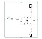
Yeah I see what you mean, that is if internal gate resistance is in parallel with source capacitance. I am considering a MOSFET model something like the one attached in the picture.
I am considering the log region (on/off) as I am interested in working out the switching losses of MOSFET. Capture.JPG
 

zuq. the only thing you need to worry about is the gate-source capacitor. once it is charged the mosfet becomes a closed switch. there is no resistor before the capacitor but there is infinite resistance after the capacitor.
 

Hit to the point ! it is exactly , thing that i tried to say !!
Best Regards
Goldsmith
 

Hi guys,

Thanks a bunch.. You are both correct indeed. And, I wasn't too far off the point either. I forwarded my query to international rectifier and this what they answered.

Quoting IRF:
The parameter Rg in the datasheet of the IRFP4004PBF is not the same as the insulation resistance of the gate structure. When driving MOSFET, a gate resistor is typically inserted between the driver and MOSFET to limit the sourcing and sinking current to the MOSFET. The IRFP4004PBF has a internal gate resistor included in the device. Yes, it will limit the switching speed because it limits the current to drive the MOSFET. The IRFP4004PBF has a very high Gate Charge which means high switching losses for this device.
 

Hi again.
You didn't talk about driver ! Yes , if you're using a driver , you have to use a series resistance , between gate and driver . to limit surge current . and if it's value be high , and your frequency if is , high , thus your mosfter will go to the linear and dissipative region .
I learned from one of my best friends : when i want find correct and best answer of my question , i should describe my question correctly , and in detail . it is exactly , thing that you didn't it !
Best Wishes
Goldsmith
 

lol..Thanks anyway
 

Status
Not open for further replies.

Similar threads

Part and Inventory Search

Welcome to EDABoard.com

Sponsor

Back
Top