Linspire
Full Member level 5
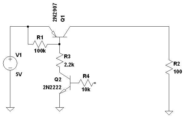
I agree, that MOSFET are preferable in terms of efficiency. But Linspire has been asking explicitely for a bipolar transistor circuit. In those cases, where the supply current doesn't vary too much, the additional base current can be almost neglected with a correctly dimensioned circuit.
Yap, I have tried search logic level mosfet in my local online shopping which doesn't sell it or maybe (I really no idea these MOSFET stuff)
http://my.element14.com
RS Malaysia | World Leading Distributor of Electronics, Electromechanical and Industrial Components
What'd you mean by correctly dimensioned circuit ?
Linspire
---------- Post added at 18:41 ---------- Previous post was at 18:39 ----------
I have used multisim ver.10; I cant find anything regarding about logic level MOSFET, and your model (KMoffett) isnt at there at all.
Linspire
")