Welcome to our site! EDAboard.com is an international Electronics Discussion Forum focused on EDA software, circuits, schematics, books, theory, papers, asic, pld, 8051, DSP, Network, RF, Analog Design, PCB, Service Manuals... and a whole lot more! To participate you need to register. Registration is free. Click here to register now.
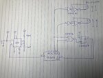
Hi everyone, I tried to design a modulo-2 to get this sequence 00,01,10,11,10,01,00. But glitch append at the ouput of the XNOR (cd4027) and trig the flipflop randomly. So do you have any suggestions to design this circuit? Thank you.
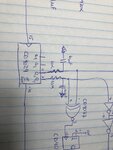
Thank you but the problem append between Q2,Q1 of the CD4029 and the input of XNOR. During the change state of Q2 and Q1 the XNOR change it output for short time. I try too put cap and resistor to make a RC delay like in the pic below.
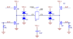
Are you really driving a relay coil like that? It's asking for problems, use a transistor to drive the coil and add a diode across the coil to catch the back spike. I'm surprised it works at all, the relay coil works in both polarities so hanging it across an inverter will release a voltage spike as the logic state changes and that could be the cause of your problem.
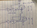
Also note that the CD4502 has an enable pin, not shown in your schematic.
Are you really driving a relay coil like that? It's asking for problems, use a transistor to drive the coil and add a diode across the coil to catch the back spike. I'm surprised it works at all, the relay coil works in both polarities so hanging it across an inverter will release a voltage spike as the logic state changes and that could be the cause of your problem.
Also note that the CD4502 has an enable pin, not shown in your schematic.
Tanks for your attention Brian.
Yes I agree I should do what you say. Look in the pic I corrected my mistake. The relay is a latching coil which requires 8mA and my buffer which has a push pull output.
See if it helps to use an XOR gate and a single invert-gate in a strategic location.
This might be the reason synchronous transmission was invented even though it's more work than asynchronous .
In simulation, to avoid such momentary change of state, I find I must do tests with various logic gates. (AND, NAND, OR, NOR, invert, etc.) To make a ring oscillator work I found it necessary to install two series invert-gates, even though it left the signal polarity unchanged.
My circuit is working now, I think I have bad connection on my bread board and also I simply put a 10k resistor between the output of the XNOR and the input clock of the FlipFlop.
This site uses cookies to help personalise content, tailor your experience and to keep you logged in if you register.
By continuing to use this site, you are consenting to our use of cookies.