Continue to Site

Welcome to EDAboard.com

Welcome to our site! EDAboard.com is an international Electronics Discussion Forum focused on EDA software, circuits, schematics, books, theory, papers, asic, pld, 8051, DSP, Network, RF, Analog Design, PCB, Service Manuals... and a whole lot more! To participate you need to register. Registration is free. Click here to register now.

Microphone preamplifier using inverted power source

Status
Not open for further replies.

hafrse

Full Member level 3
Joined
Aug 6, 2007
Messages
169
Helped
1
Reputation
2
Reaction score
3
Trophy points
1,298
Activity points
2,413
Hello,

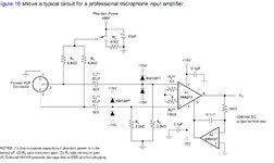
I am trying to build a microphone amplifier based on a design given by the manufacturer of the INA217 OP amplifer.
The equipment where this preamplifier will be applied to has only inverted supply: chassis is at 0V and power supply is -10V to the instrument.
The preamplifier uses GND , +15, -15 supply. I have a small power supply inverter board that generates -15v and +15v form a +10v, however, I can connect 0v from the instrument to Vcc of the this inverter and -10 from the instrument to GND of the inverter , I can get -15 and +15 v with respect to the GND of the inverter but I can not connect the GND of the inverter to the instrumnt chassi "GND" since its haigh at 10v and it shorts the inverter Vcc. How can I cope with this problem?

Thanks for any help
 

Attachments

  • Untitled (1).JPG
    Untitled (1).JPG
    222 KB · Views: 133
Last edited:

Hi,

The problem seems to be the power supply and it´s wiring ..combined with an "unknown instrument".
But your schematic does not show this.
I think it´s a good idea to draw a sketch about the power supply and wiring...

From what I see, just use an isolated DCDC converter for 10V --> -15V, +15V then you are free to connect whatever you want.

Klaus
 

    hafrse

    Points: 2
    Helpful Answer Positive Rating
Hi,

The problem seems to be the power supply and it´s wiring ..combined with an "unknown instrument".
But your schematic does not show this.
I think it´s a good idea to draw a sketch about the power supply and wiring...

From what I see, just use an isolated DCDC converter for 10V --> -15V, +15V then you are free to connect whatever you want.

Klaus
You are right, isolated power supply will work , isolated supply will provide a GND to the preamplifier
--- Updated ---

 
Last edited:

Your high voltage phantom powered microphone must be a "condenser" type that already has an impedance converter/preamp. Then why do you need this fairly low input impedance preamp?
 
  • Like
Reactions: hafrse

    hafrse

    Points: 2
    Helpful Answer Positive Rating
There's no problem to modify the circuit to use -10 V negative supply. Of course it can't provide 48V phantom power without a DC/DC converter. Maximal output swing will be lower but still sufficient. AC coupling needed to block the output DC offset.
 
  • Like
Reactions: hafrse

    hafrse

    Points: 2
    Helpful Answer Positive Rating
I will not use a +48V powered microphone and will not have a power for +48v, this circuit should apply to both according to the author (?) here is the pdf, page 13 https://www.ti.com/lit/ds/symlink/ina217.pdf?ts=1641586224082&ref_url=https%3A%2F%2Fwww.google.com%2F. As porposed, I will use an isolated +15/-15 converter and use the preamplifier "as is". Any drowbacks or comments?
--- Updated ---

Your high voltage phantom powered microphone must be a "condenser" type that already has an impedance converter/preamp. Then why do you need this fairly low input impedance preamp?
I will not use a +48V powered microphone and will not have a power for +48v, this circuit should apply to both according to the author (?) here is the pdf, page 13 https://www.ti.com/lit/ds/symlink/i...24082&ref_url=https%3A%2F%2Fwww.google.com%2F C1 and C2 will be none-polar type when not applying +48V. As porposed by KlausST
I will use an isolated +15/-15 converter and use the preamplifier "as is". Any drowbacks or comments? thanks
 
Last edited:

Hi,

As porposed, I will use an isolated +15/-15 converter and use the preamplifier "as is". Any drowbacks or comments?
Use a low noise DCDC converter and/or use additional filter.

Klaus
 
  • Like
Reactions: hafrse

    hafrse

    Points: 2
    Helpful Answer Positive Rating
Hi,


Use a low noise DCDC converter and/or use additional filter.

Klaus
I will use this one https://www.tracopower.com/int/series/ten-6win , any advice on external filering? thanks
--- Updated ---

Is the input signal from a microphone? Which type of microphone?
Non phantom powered microphones like the Sennheiser MD 421 II but I might add a switch and a +48v supply in the fulture according to the schemtics.
History : The musical equipment I have is a Nagra IV-SJ and has negative power , it lacks any type of the (was) availble optional microphone preamplifiers (standard version does not come with preamplifiers) so I am building one as proposed above.
 
Last edited:

Hi,

I opend the amplifier datasheets to find out power requirements.
I'd say one can expect far below 0.5W.
But the DCDC converter is able to supply 6W.
So maybe you run it at 5% of the rated power. You risk to force it into discontinous (burst) mode, which causes a lot of rather low frequency voltage ripple. Hard to filter out.

Filter design depens on whether you need to suppress switching frequency or burst mode ripple.
For digital systems this usually is no problem, but for low noise audio it may be..

I recommend to do tests on a real circuit.

Klaus
I have the amplifer circuit built on a board , I tested the power consumption with 2x INA217 and 2x OPA237, it gives a total of about 2.1 Watts, but here what the manufacturer says about the DC-DC converter:

"The TEN 6WIN series is designed for an optimized cost/performance ratio of DC/DC converters with output power of 6 Watt.
General features like no minimum load requirement, overload protection, internal filter for EN55022 class A and high efficiency make these converters easy to design in. With the popular DIP-24 standard package they are also a drop in replacement for many cost critical applications.

The TRACO TEN 6WIN series is a new range of high performance dc-dc converter modules with 6W output power, featuring ultrawide 4:1 input voltage ranges and tight output voltage regulation. The product comes in a DIP-24 package with industry standard footprint. Excellent efficiency allows an operation temperature range of -40°C to +85°C . Standard features include overload protection. Typical applications for these cost optimized converters are battery powered equipment, instrumentation, datacom and industrial electronics."


Taken from
https://www.tracopower.com/int/series/ten-6win

The DC-DC converter will arrive at the end of next week.
 
Last edited:

Hi,

"cost optimized" is a synonym to "cheap" ...
this may mean it is not optimized for low output voltage ripple.

I can´t say they are good or they are bad. TRACO usually is a rather good brand with good products.
But "good" for one application does not necessarily mean it is also good for another application.
It´s a question of requirements and specifications.

--> So let´s see what your tests show.

Klaus
Yes , you are correct, I will setup and make some readings under load with oscilloscpe/fft analyzer when it arrives at the end of next week. Thanks!
--- Updated ---

Hi,

"cost optimized" is a synonym to "cheap" ...
this may mean it is not optimized for low output voltage ripple.

I can´t say they are good or they are bad. TRACO usually is a rather good brand with good products.
But "good" for one application does not necessarily mean it is also good for another application.
It´s a question of requirements and specifications.

--> So let´s see what your tests show.

Klaus
I found in the data sheet that ripple and noise at 20 Mhz bandwiidth is 80 mVp-p max. let see how it looks like at +15/-15v output .
--- Updated ---

Hi,

"cost optimized" is a synonym to "cheap" ...
this may mean it is not optimized for low output voltage ripple.

I can´t say they are good or they are bad. TRACO usually is a rather good brand with good products.
But "good" for one application does not necessarily mean it is also good for another application.
It´s a question of requirements and specifications.

--> So let´s see what your tests show.

Klaus
I located the manufaturer ripple/noise test at full load for the exact model TEN 6-2423WIN (+15/-15V 6W). I would expect the same with the one I receive :) , do you see any majour problems there ?
 

Attachments

  • ripple.jpg
    ripple.jpg
    193.7 KB · Views: 105
Last edited:

Hi,
do you see any majour problems there ?
two things:
* you should trust the TRACO datasheet.
* but here it clearly shows "@ full load". --> Not burst moode.

If it enters burst mode, then the waveform will look much different wich a lot of low frequency components.
.. yes: if..

Klaus
 
Hi,

two things:
* you should trust the TRACO datasheet.
* but here it clearly shows "@ full load". --> Not burst moode.

If it enters burst mode, then the waveform will look much different wich a lot of low frequency components.
.. yes: if..

Klaus

Normally, at what % load does a dc-dc converter enters burst mode? or is it different on different specific design? counting that consumtion will be around 2.1 Watts from the amplifier, this will be about 35% of full power (6 Watts).
 

Hi,

There is no "normal threshold". Some never enter burst mode.
With 2.1W fdrawn from a 6W converter .. I don´t think it enters burst mode.

But again: Let´s see what your tests show.

Klaus
 

Hi,

There is no "normal threshold". Some never enter burst mode.
With 2.1W fdrawn from a 6W converter .. I don´t think it enters burst mode.

But again: Let´s see what your tests show.

Klaus
thanks!
 

I see that the microphone is a 200 ohms dynamic (coil and magnet) with a +8dB presence peak at 5kHz and you need the preamp to feed your 50 years old tape recorder (I remember tape).
 
  • Like
Reactions: hafrse

    hafrse

    Points: 2
    Helpful Answer Positive Rating
Status
Not open for further replies.

Similar threads

Part and Inventory Search

Welcome to EDABoard.com

Sponsor

Back
Top