Continue to Site

Welcome to EDAboard.com

Welcome to our site! EDAboard.com is an international Electronics Discussion Forum focused on EDA software, circuits, schematics, books, theory, papers, asic, pld, 8051, DSP, Network, RF, Analog Design, PCB, Service Manuals... and a whole lot more! To participate you need to register. Registration is free. Click here to register now.

microcontroller and RTC based bell controler with an LCD

Status
Not open for further replies.

7@rB

Junior Member level 3
Joined
Feb 19, 2012
Messages
25
Helped
1
Reputation
2
Reaction score
1
Trophy points
1,283
Location
Lebanon
Activity points
1,458
hello everybody,
I have to design the above project, the main goal is to have a bell controller but in addition I want my system to be based on a RTC and the bell should rings according to a predefined specific times although I have to represent the current time with an LCD. Any help?
 

Do you have to use any particular microcontroller?

Some of the Microchip PIC range have a built-in RTC circuit, so you don't have to make an RTC in software. Something like that would be the easiest solution.
 

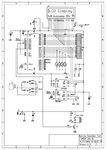
this circuit is ds1302 based school bell.
if u interested i will post all details.
timer.jpg
 
  • Like
Reactions: 7@rB

    7@rB

    Points: 2
    Helpful Answer Positive Rating
FoxyRick,
I dont have, I am confused for that ! for me, the problem is about the features of my system (LCD, Ethernet interface , bell controlling according to the RTC) , which microships have a built in RTC? do you have an idea if the pic30f2010 include it?


matthai,
thank you, yes I am but I have some questions, what is the use of the switches (sw1,sw2,sw3, and sw4)? what is the function of J4? and u4?
 

You did not mention ethernet before - that makes things more complicated.

For PICs with RTC, go to the link below and click "H/W RTCC" on the right. There are a lot, but not the dsPIC30F2010

**broken link removed**

For Matthai's circuit, let me guess:

The switches are to set the clock time and alarms.
J4 is a jumper to connect the bell.
U4 is an EEPROM to store the programmed alarms.
 
  • Like
Reactions: 7@rB

    7@rB

    Points: 2
    Helpful Answer Positive Rating
any help with programming the 8051 chip in the circuit given above by matthai?
 

hi,
i am sending all, including,circuit,pcb,asm & hex files to u.


best wishes
matthai.
 

Attachments

  • TIMER.pdf
    200.4 KB · Views: 138
Last edited:
  • Like
Reactions: 7@rB

    V

    Points: 2
    Helpful Answer Positive Rating

    7@rB

    Points: 2
    Helpful Answer Positive Rating
thank you dear, really you helped me :)
dear just I want to ask you if it's tested? I am going through it now.
also, can I have the values of the crystal u used in junction with the microcontroller (X2, X1 is sure 32.768Khz) also do u use the 8051 or 8052?, btw does it make a difference?
 

hi 7@rB,
i did this long years back,and also tested.
i was using 89c52.it's only difference is memory,here both will work with some program modification.
crystals x1= 32.768 kHz & x2 =4 MHz.
 
  • Like
Reactions: 7@rB

    7@rB

    Points: 2
    Helpful Answer Positive Rating
Status
Not open for further replies.

Similar threads

Part and Inventory Search

Welcome to EDABoard.com

Sponsor

Back
Top