MissP.25_5
Newbie level 6
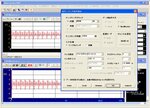
 In this experiment, a person's voice was recorded on a mic as the analog source. And then the analog data was converted into digital data so that the program on the PC could read it and then the digital data was converted into Analog again to reproduce the recorded voice. I attached the results of the last part of the experiment. I am not sure what method this is. What I do know is that it is done to check whether the digital data was transmitted accurately or not by using the A/D and D/A conversion program on the PC. Can someone explain to me what exactly does that picture mean? What is being done here? The AD and DA waveforms are the same after adjusting the trigger level (Voltage). The writings are just the settings of the sampling. The sampling frequency is 8kHz. I want to know what does the trigger level have to do with checking the accuracy of the digital transmission? What is the disadvantage of this method and how to improve it?
Last edited: