Continue to Site

Welcome to EDAboard.com

Welcome to our site! EDAboard.com is an international Electronics Discussion Forum focused on EDA software, circuits, schematics, books, theory, papers, asic, pld, 8051, DSP, Network, RF, Analog Design, PCB, Service Manuals... and a whole lot more! To participate you need to register. Registration is free. Click here to register now.

Measuring resistance of NaCl solution using Atmega16

Status
Not open for further replies.

ark5230

Advanced Member level 3
Joined
Jun 29, 2009
Messages
862
Helped
163
Reputation
324
Reaction score
140
Trophy points
1,323
Location
India
Activity points
6,187
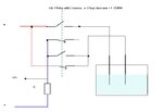
I am trying to measure resistance of NaCl solution using conductivity cell 1 cm x 1cm.
The cell is connected to +5V supply of Atmega16 via 47K.
The other end of cell is ground.
Measuring voltage across cell did not give meaningful results.
I tried changing 47K to 200K on higher side in steps, and lower side to 10K.
In all the cases there is very marginal change in readings.
Is the input impedance of the ADC responsible for this as the resistance of the cell with solution is expected to be in the range of 20K to 300K.
Any clue?
Is the electrolyte nature of solution the culprit!!
 

Although you have not provided much more details concerning working of the circuit and the cell apparatus, seems like a classic case in which the measurement process interfere itself on result.

Note that the ions dissolved on water, after energized by a continuous current between two electrodes, needs a certain time for stabilize the balance between ions that migrate up to each electrode side, and even a small current is able to produce an electrolysis reaction.

I would suggest you take several measured samples - took along a sparse period - for obtain final result from average.


+++
 
I would recommend you to do an AC measurement. DC current through an electrolyte gives an internal EMF due to chemical reactions and ion concentrations. So you are right regarding electrolytes.

When using AC you can avoid these problems. When meausing EC in the range of 0.1 S, using around 2..4 kHz is a good starting value. Measuring very low conductivity requires a lower frequency, otherwise you will measure current due to the high relative epsilon (80) of water.

You also have to make sure that your electrodes are in good (clean non-corroded) condition (so cleaning with demi-water after usage).

If you want really high accuracy, you may use a 4 electrodes setup where two electrodes are used to supply the current, and the other two are used for measuing the voltage.
 
Thanks a lot Andre_teprom the conditions you pointed out prevail in the electrolytic cell and electrolysis does occur.
Additionally here the currents through the cell are of the order of 5 mA and thus appreciable reaction is present at the surface of electrodes. In fact there is a deposition at the electrodes that is major cause. I will attend to these things firs and update.

Thanks WimRFP the details cited are really useful. I feel you have answers to many more questions related to this experiment I am trying. I woul share all the relvent details so that your guidance will help figuring out the issues and resolving them. I am proceeding to procure necessary things to correct existing drawbacks.
 
Last edited:

The problem relates to the conductivity cell electrode condition (thick coating deposition) and also the quality of water used, additionally the membrane used had defect.
Correcting these issues improved performance and things are taking shape but still needs improvement. I am trying to resolve the issue that after a few minutes the resistance of cell reaches a low value and slowly starts increasing again.
Stirring the solution also showed improvement.
 

The problem relates to the conductivity cell electrode condition (thick coating deposition)
after a few minutes the resistance of cell reaches a low value and slowly starts increasing again.
Can we conclude that you are still trying DC conductivity measurement?
 
Yes true I am trying DC conductivity.
This is pilot experiment.
The setup is in development and testing.
The current through the cell is few milliamperes so appreciable electrolysis and deposition is likely to be there as it appears.
 

Electrical double-layer with respective polarization voltage will be observed with any DC current level, I suppose.

If you supplement your present circuit with a DPDT analog switch and run it at a few 100 Hz commutation frequency, it might be still useable.
 
If you supplement your present circuit with a DPDT analog switch and run it at a few 100 Hz commutation frequency, it might be still useable.

Not clear to me.
I am taking readings at 5 second intervals.
does it mean that it should be given voltage only at the moment I am reading in the resistance of the cell.
I am trying to find DPDT analogue switches for this purpose thanks for kind guidance.

These analogue switches seem to have sizable internal resistance 50 to 100 ohms or even more (4016)
 
Last edited:

@ark5230: You have a micrcontroller, ADC, etc. By implementing an AC scheme, you will eliminate lots of hard to assess variables. As you are measuring relative high cell impedance, you can use relative low AC frequency that can be handled by your ADC. You could even switch between two AC frequencies to assess whether the frequency is too low, or you need to clean the electrodes.

I use 2 kHz, but that is because of the higher conductivity of the fluids, you can likely use a lower frequency.
 

@ark5230

The method suggested by @WimRFP seems the most appropriate for achieve your need, rather than through a DC current as you are trying to do, due to the reasons already pointed on post #2.

Note that such approach can also be employed on promising systems for monitoring lead-acid battery health status:

See that:


+++
 
Hi,

a simple way to generate AC is:
* connect the (now GND) side of the cell to a AVR port(1).
* Now you can switch the AVR port to 0 and VCC.
* For your ADC input (2) you then need two resistors - one to GND and the other to VCC. Mind: zero is now in the middle of the ADC range.
* To improve precision you can measure voltage of the switching AVR port (1) and calculate the ratio with the ADC input (2).

Hope this helps
Klaus
 

andre_teprom This seems to be a reliable technique, I will explore the same.
The link relates to measurement of cell resistance in the range of milliohms (low resistance regime) which otherwise could be difficult to measure. In the present case the resistances are on higher side, however I will study the details and try to adopt the same to present application. Thanks a lot.

KlausST
I am trying to understand this concept, As I could understand, it is generating square wave pulses rather than AC, Not sure if this works.
Thanks for guidance.
 

It is easy to reverse the polarity accross the electrodes with a relay 2N0 + 2NC (gold contacts)
or drive 2 CD4016 elements trough logical inverser and 2 elements direct command
with only one commande
and get the measure across R value... current is always same direction.. so voltage also..
and you can reverse every x seconds or every x measures to keep clean electrodes...
 

Attachments

  • Nacl_measure.jpg
    Nacl_measure.jpg
    24.3 KB · Views: 139
Hi,

paufjujo: is a good circuit.
one hint: www.maxim-ic.com have CMOS switches called "phase reversal switches" that do exacetely this within an 8 pin IC.

**
here my circuit without extra IC:
schem2.png
switch PB5 with 50% duty cycle, maybe 10Hz.
R1 with D1 is for AVR protection, R1 and C1 forms a lowpass filter. (maybe some kHz).
ADC6 is the reference path for your measurement, R2 with C2 should be your anti-aliasing filter
ADC7 is your signal path for your measurement, R5 with D5is protection, R5 and C3 should be your anti-aliasing filter
R4 with R3 is bias voltage.

With that circuit you can correlate your ADC with the 10Hz frequency to filter out all other unwanted frequencies (noise, line frequency...)
Also it´s fully ESD protected. With a good choice of resistor an capacitors you get very stable values.
(mind that with high ohmic cell the ADC reading is about the center of your ADC range.
Signal is positive and negative - referenced to this center.

Hope this helps.
Klaus

edit1: oops, there was a wrong picture...
 
paulfjujo
Thanks a lot. This gave me clear picture of what needs to be done.
One thing is that the resistance of CD4016 may be of concern as this becomes comparable with the cell resistance (electrolyte).
I will figure it out. The resistance of the cell is less than 1K in the present working conditions.

KlausST

I am new to this device and examine carefully, sounds good and looks like this will solve the issue if CD4016 could not because of its resistance. Thanks for good advise. :grin:
 
Last edited:

Status
Not open for further replies.

Similar threads

Part and Inventory Search

Welcome to EDABoard.com

Sponsor

Back
Top