Continue to Site

Welcome to EDAboard.com

Welcome to our site! EDAboard.com is an international Electronics Discussion Forum focused on EDA software, circuits, schematics, books, theory, papers, asic, pld, 8051, DSP, Network, RF, Analog Design, PCB, Service Manuals... and a whole lot more! To participate you need to register. Registration is free. Click here to register now.

[SOLVED] matching 5 transistors with 2 fingers

Status
Not open for further replies.

preethi19

Full Member level 5
Full Member level 5
Joined
Jun 30, 2014
Messages
273
Helped
0
Reputation
0
Reaction score
1
Trophy points
16
Activity points
3,474
Hi i need to match 5 transistor (A,B,C,D,E) each having 2 fingers. So the total is 10. So 3x4=12.. So i add 2 dummies (0) and i have laid them as

D E 0
A B C
-------
A B C
D E 0

Is this a right way to do. Or should i make an even square matrix by adding 4x4=16... So by adding 6 dummies. Am i missing something??? Any tip while generally doing layout. Thanks!!!!
 

Hi,

I am not a professional on layout design, however, I know from my advisor that once he adviced me to put dummy transistors at the beginnings and alsı at the ends of each line. So the real transistors located in the middle. I think this is related to matching all the nodes of the transistors. For example in your illustration, if transistor D and E are intended to be matched, although they are at the same sizes they are not matched exactly. Because left of the transistor D is blank but transistor E has neighbours at both sides. So the impedances that are seen by the nodes of D and E are different. If you also add a dummy transistor to the left of transistor D, D and E would be better matched.

All in all, I think it is better to add some dummy transistors at both sides.
 
oh thank you for the reply.... All A,B,C,D,E are exactly of the same size. And D and E alone are not required to be matched. All these 5 belong to a current mirror and need matching of all with one another. And from u said i can see yes E has neighbours and D doesn't. So its like for well maching we need dummies to the side.. So in that we can also tell A and C also dont have neighbours while B has on its both sides A and C.. So then it wll be like i have to put dummies on the side of A,C,D. Also then E is towards the end (ie below E), should i put a dummy near it too??? Then its pretty much covering the whole thing by dummy like below becoz all needs to be matched.


0 D E 0 0
0 A B C 0
-----------
0 A B C 0
0 D E 0 0
 

Actually i forgot to mention that surrounding the whole structure i can put a bulk ring. so I dont think i have to use other dummies except the 2 dummies i mentioned first. So the first structure with the bulk ring around does it make the matching right??? Thanks again!!!
 

... the first structure with the bulk ring around does it make the matching right?

Not at all. A bulk ring around the structure even could make the matching worse, if it were too close. The meaning of dummies is to keep the same environment at both sides of the transistors which have to be matched. Means you need dummies next to all your transistors at the end of the chain.
 
Thanks erikl i am very clear now. I will be using a whole chain of dummy transistors arround the above structure. Making a chain of dummy around the structure is bringing about 14 transistors all around and dummy transistors increase parasitic capacitance. Just of out curiosity wat if i use a bulk ring around each set like below (the dashed lines are bulk surrounding each set)... Is this wrong... Doing this will it cause any effect???

-----------
|0 D 0 E 0|
-----------
|0 A B C 0|
------------
|0 A B C 0|
------------
|0 D 0 E 0|
------------

The reason making bulk ring around each set so i can avoid using dummies above and below D and E. Since if A and D need matching then A has neighbours. But D doesn't have same surrouding as A requiring me to put a dummy below/above D and E. The side dummies i can't avoid even with a bulk ring but the up/ down dummies can be avoided right if i do it this way. Would be really great if helped with this!!!!!
 

You don't need a bulk ring around nor between the rows for good matching. Such rings are for isolation, not for matching - they can even make matching worse because of WPE effects.

For good matching we use common centroid (point-symmetric) layouts. I'd suggest you change your layout to

0 D 0 E 0
0 A B C 0
0 C B A 0
0 E 0 D 0

or

0 A B C D E 0
0 E D C B A 0

... without any bulk guard rings/rows. So each transistor has the same environment - seen in total (for side dummies used, the longer side extension (W||L) of all transistors should be vertical). Even if the routing is more complex - and you possibly should see your routing is symmetrical too, if the total capacitance of the connection is important.

... Making a chain of dummy around the structure is bringing about 14 transistors all around and dummy transistors increase parasitic capacitance. Just of out curiosity wat if i use a bulk ring around each set like below (the dashed lines are bulk surrounding each set)... Is this wrong... Doing this will it cause any effect???

-----------
|0 D 0 E 0|
-----------
|0 A B C 0|
------------
|0 A B C 0|
------------
|0 D 0 E 0|
------------

The reason making bulk ring around each set so i can avoid using dummies above and below D and E. Since if A and D need matching then A has neighbours. But D doesn't have same surrouding as A requiring me to put a dummy below/above D and E. The side dummies i can't avoid even with a bulk ring but the up/ down dummies can be avoided right if i do it this way. Would be really great if helped with this!!!!!
 
Hi i tried laying out the transistors as mentioned above. the matching was good but it was told that it is required to have sufficient biasing and without a bulk rows inbetween it would not give sufficient biasing to transistor B since it is in the middle of the layout. So can you kindly let me know how to lay the bulk for the above set of matched transistors. Becoz i understood the WPE effect too and why we should not put the bulk rows inbetween but now i am asked to fix the biasing. since a bulk ring is also used to give bulk connection for the transistor.

Also can i understand why isolation is required from the following link
https://www.tf.uni-kiel.de/matwis/amat/elmat_en/kap_5/backbone/r5_1_4.html
I can understand so incase if inbetween transistors der is a wire between source and drain it can cause it to become a parasitic transistor.
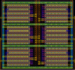
while learning layout i was given this eg to start with and in this layout matching of M1 and M2 was required. I have attached the image. They have used bulk rows inbetween and yet these transistors need matching. Wont it affect the matching more??? Pls help... Very confused on when to use isolation and when not and if not using bulk rings how to sufficiently bias all transistors. Would be really great if someone could help!!!
match.png

They have laid as

A B
-----
B A
-----
A B (--- is the bulk ring)

So a bulk ring is isolating A and B in the vertical direction but then
A B inbetween them we have no isolation so wont a parasitic transistor form here????
 
Last edited:

Also if i don't isolate them and if i use a metal connection that passes inbetween source and drain of different transistors then won't that result in parasitic transistor??? becoz even if we want all transistors matched we would not require a parasitic transistor connection between source and drain of A and B respectively even if they are matched.
 

... now i am asked to fix the biasing. since a bulk ring is also used to give bulk connection for the transistor.
Ok. If they want it, they should get it.

Also can i understand why isolation is required from the following link
https://www.tf.uni-kiel.de/matwis/amat/elmat_en/kap_5/backbone/r5_1_4.html
I can understand so incase if inbetween transistors der is a wire between source and drain it can cause it to become a parasitic transistor.
You should have read on:
The solution is to make the threshold voltage larger than any voltage that may occur in the system. The way to do this is to increase the local thickness of the insulating dielectric.
Modern CMOS circuits always have either this thick field oxide (TOX), or
for 0.25um and smaller process technologies, shallow trench isolation (STI) ... is more commonly used to isolate the transistors. In STI fabrication, trenches are etched into the wafer and filled with silicon oxide to isolate the islands of transistor active area.
(Quoted from Lee Eng Han et al. © 2005: CMOS Transistor Layout KungFu). Suggest to read this article!

So, no problem with wires (leading normal voltages) between transistors any more, due to TOX or STI isolation.


... while learning layout i was given this eg to start with and in this layout matching of M1 and M2 was required. ... They have used bulk rows inbetween and yet these transistors need matching. Wont it affect the matching more???
Not, if they use the same (and sufficient, because of WPE) spacing between and around the transistors.

They have laid as

A B
-----
B A
-----
A B (--- is the bulk ring)

So a bulk ring is isolating A and B in the vertical direction but then
A B inbetween them we have no isolation so wont a parasitic transistor form here????
No, s. above. But for good matching, a vertical and a surrounding bulk ring should also be inserted, with the same (sufficient) spacing around all transistors, as mentioned above.

Also if i don't isolate them and if i use a metal connection that passes inbetween source and drain of different transistors then won't that result in parasitic transistor??? becoz even if we want all transistors matched we would not require a parasitic transistor connection between source and drain of A and B respectively even if they are matched.
This is no problem due to STI, s. above!
 
If you want match this in common centroid mode, According to my knowledge below one is good,
O A B C D E O
O E D C B A O
it will obey all conditions of matching like compactness,dispersion,orientation,coincide and symmetry
 

Status
Not open for further replies.

Part and Inventory Search

Welcome to EDABoard.com

Sponsor

Back
Top