Continue to Site

Welcome to EDAboard.com

Welcome to our site! EDAboard.com is an international Electronics Discussion Forum focused on EDA software, circuits, schematics, books, theory, papers, asic, pld, 8051, DSP, Network, RF, Analog Design, PCB, Service Manuals... and a whole lot more! To participate you need to register. Registration is free. Click here to register now.

Make: Electronics experiment #10 (trouble reading transistor)

Status
Not open for further replies.

rhodium

Newbie level 2
Joined
Mar 24, 2016
Messages
2
Helped
0
Reputation
0
Reaction score
0
Trophy points
1
Activity points
22
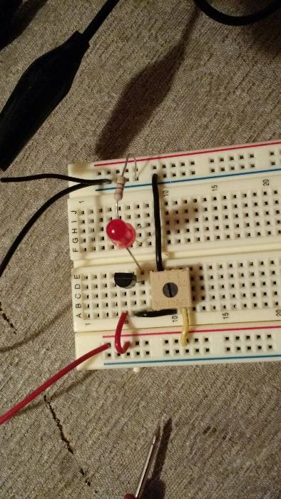
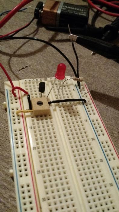
Here is the circuit I put together and the directions I followed. I set up my meter as instructed and get 9.37 volts on the collector and 0.18 volts on the emitter, but when I touch my red probe to the base it reads nothing.

I'm using a black plastic PN2222A transistor from the Make: Electronics kit. I tried using a new transistor from the same bag but got the same result. Thanks for your help.


Last edited by a moderator:

I'm not sure what the tutorial aims to achieve as the emitter follower configuration has no voltage again anyway.

However, taking a practical approach:

1. the voltage at the base (middle) pin is mostly set by the position of the potentiometer. Check that with it turned fully one way you get 0V on the base and fully the other way you get 9V. If you do not get those voltages, the potentiometer is wired incorrectly.

2. when you have the base voltage changing between 0V and 9V, the emitter pin should follow the base voltage but be about 0.7V lower. In other words it should go between about 8.3V and 0V as you turn the potentiometer from end to end. Note that it can never go below 0V, when the base has 0.7V or less on it, the emitter will stay at zero.

Let us know when you have 1 and 2 working.

Brian.
 

It looks like they are trying to show you that the base will always be about 0.7 V higher than the emitter.

Naturally, the LED will only come on as long as the base voltage is higher than the LED forward voltage plus about 1 V.
 

Attachments

  • b_e_volts.png
    b_e_volts.png
    11.4 KB · Views: 81
Last edited:

I'm not sure what the tutorial aims to achieve as the emitter follower configuration has no voltage again anyway.

However, taking a practical approach:

1. the voltage at the base (middle) pin is mostly set by the position of the potentiometer. Check that with it turned fully one way you get 0V on the base and fully the other way you get 9V. If you do not get those voltages, the potentiometer is wired incorrectly.

2. when you have the base voltage changing between 0V and 9V, the emitter pin should follow the base voltage but be about 0.7V lower. In other words it should go between about 8.3V and 0V as you turn the potentiometer from end to end. Note that it can never go below 0V, when the base has 0.7V or less on it, the emitter will stay at zero.

Let us know when you have 1 and 2 working.

Brian.

Adjusting the potentiometer all the way in either direction or anywhere in between gives me the same voltage on the emitter and no reading on the base. I've checked numerous times to ensure the potentiometer is at the correct spot on the breadboard with the pins in the correct terminals.

When I first took the potentiometer out of the bag, I noticed that one of the pins was depressed. I assumed that shouldn't be, so I bent it out to match the other pins. Should I not have done that? Depressing it again hasn't made any difference.
 

If you are getting no reading when you connect the red probe to the base and black probe to the negative voltage input ( when the circuit is all attached and voltage supplied) that means your variable resistor or potentiometer is dead.
 

Agreed, the potentiometer is the only source of voltage to the base, all there is inside it is a track of partially conducting carbon material with a metal wiper that traverses it from end to end as you turn the screw slot. At each end it becomes directly connected to one of the end pins so it should always give 0V and 5V, even if the middle was burned out. Just check AT THE potentiometer that you have 0V and 5V, if you have and the other pin doesn't change from zero, it is damaged I'm afraid.

Brian.
 

2 ways.
1 - Remove the connection from the wiper to the base. Measure the voltage between ground and the wiper while you turn the pot. The voltage should vary between 0 and 9 volts.

2 - Ohm it between the extremities. This should give the value marked on it +/- some percentage. If that's ok then ohm it from one end and the wiper while you turn it. This should give 0 to whatever the max value is.

If you get different values replace it, they're cheap enough not to worry about.

Make sure it's connected correctly. If, for example, the wiper is grounded and you turn it up it wll effectively short the supply. This is likely to burn out the last stretch of carbon track and give the effect you're reporting.

When in doubt, always measure.
 

Status
Not open for further replies.

Similar threads

Part and Inventory Search

Welcome to EDABoard.com

Sponsor

Back
Top