Continue to Site

Welcome to EDAboard.com

Welcome to our site! EDAboard.com is an international Electronics Discussion Forum focused on EDA software, circuits, schematics, books, theory, papers, asic, pld, 8051, DSP, Network, RF, Analog Design, PCB, Service Manuals... and a whole lot more! To participate you need to register. Registration is free. Click here to register now.

LPF for RTD Measuring

Status
Not open for further replies.

khaled maher

Newbie
Joined
Aug 21, 2006
Messages
2
Helped
0
Reputation
0
Reaction score
0
Trophy points
1,281
Activity points
1,310
Good Day

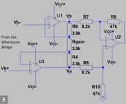
For my RTD, I will use a Whetstone Bridge connected to Instrumentation amplifier as shown below.
The sensor will be installed in a small factory beside a number of three phase motors so I decided to add an active low pass filter.
But I have a number of questions:
1. How much the cuttoff frequency "Fc" suppose to be. i.e. does the noise range for such a workplace could be known ??
2. Should I apply the filter after the Whetstone Bridge or after the instrumentation amplifier or it doesn't matter ??
3. Does the CMRR of my Op-Amps would works as a filter or it is better add an active filter ??

Thank You
 

Attachments

  • Untitled.jpg
    Untitled.jpg
    71 KB · Views: 102

Hi,

I have to aspects for choosing the LPF location:
* if you want to suppress ESD, EMC or some other noise coming from the sonsor or cabling: I´d put the filter in front of the first OPAM. This mainly is to slow down dV/dt and avoid to overdrive the OPAMP´s input stage.
* if you want to suppress general noise, also the noise of the OPAMP, then put the filter after the OPAMP.

Fc depends on what frequency (from sensor) you are intereseted in. lower fc results in better suppression for high frequency noise. But also causes some amplitude drop and phase shift..

CMRR has nothing to do with noise filtering. It´s a measure of how much the output voltage is influenced by changing the common mode input votage. But in your case common mode input voltage is ratherfixed to V_sensor/2.
Do you expect some common mode noise?

Klaus
 

I don't see a purpose of Wheatstone bridge for RTD measurement. Usual configuration is single ended voltage divider or current source supplied RTD. Differential amplifier is needed for three- or four-wire measurement (elimination of cable resistance), but also different from Wheatstone.
 

I don't see a purpose of Wheatstone bridge for RTD measurement. Usual configuration is single ended voltage divider or current source supplied RTD. Differential amplifier is needed for three- or four-wire measurement (elimination of cable resistance), but also different from Wheatstone.
Agreed. A Wheatstone bridge is used for devices with small relative change. Current source works fine.

I’d put the filter right after the sensor. You can also add some gain to the filter so you only need one opamp.
 

Status
Not open for further replies.

Part and Inventory Search

Welcome to EDABoard.com

Sponsor

Back
Top