sarinsukumar
Newbie level 4
I had posted a thread about "low cost pickit2 clone" making
]
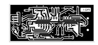
after many reviews i have made it more simple. Like some thing u can make it with the controller (pic 18F2550) and some discrete components which are easily available.
No mosfets (difficult to find) not even bat 54 (schottky diode) . just few transistors and diodes.
which support programing and debugging + 5 and 3.3 V device support with protection circuitry.
You can find the full article here with schematics.
https://electronicsadvices.blogspot.com/2009/04/full-featured-pickit2-clone.html
]
after many reviews i have made it more simple. Like some thing u can make it with the controller (pic 18F2550) and some discrete components which are easily available.
No mosfets (difficult to find) not even bat 54 (schottky diode) . just few transistors and diodes.
which support programing and debugging + 5 and 3.3 V device support with protection circuitry.
You can find the full article here with schematics.
https://electronicsadvices.blogspot.com/2009/04/full-featured-pickit2-clone.html