ChAndrea
Newbie level 4
Hi all,
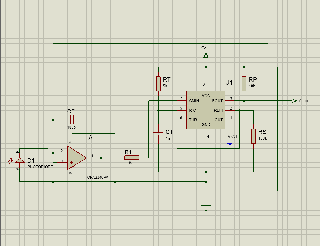
I designed a discrete light to frequency converter using a LM331 in a "precision voltage to frequency converter" configuration.
I attached the schematics. This circuit works well when I use a controlled voltage (and a resistor) or a current source as the input, but when I put the photodiode the frequency output slowly drifts over time in response to a constant light (3 leds inside a shielded box with the photodiode).
The drift is sometimes positive and sometimes negative, with a really slow dynamic. The problem is I could not find any deterministic explanation to this phenomena (maybe a temperature drift, I read is around 1-2% of the signal every 5C°). The drift is usually higher if the current flowing is higher, around 10-50 nA per 10secs with a 5uA current, slowly stabilizing after a light step.
The photodiode is ideally unbiased, but during operation each time a "reset" occurs a low reverse bias is applied because of the finite op amp GBW. This could affect accuracy but cause a drift (with such a slow dynamic)?
I checked the bode plot of op amp integrator using a classical photodiode model, with a shunt resistor and capacitor. Everything should work fine.
The photodiodes are PIN (I tried several of them). To measure the frequency I'm using a Tektrotronix 2022c oscilloscope, but I obtain the same results using a microcontrollor as a frequency meter.
I'm working with high resolution (10Khz per 1uA circa) so this could be a normal behaviour which I could not see using a transimpedance amp.
I'd like to know if you ever encountered something similiar, and if I'm missing some pheomena.
Thank you for your help and time.
Andrea.