neazoi
Advanced Member level 6
Does "headed up" mean heating up?
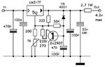
Can't you simply calculate the heating power? (12V - 4.288V) x 440mA= 3.4W and a medium size heatsink is needed. The minimum input to the LM317 can be 4.288V + 1.8V= 6.088V and the heating will be 1.8V x 440mA= 0.8W and if you use the TO-220 package and the LM317 is not enclosed then no heatsink is needed. I would use a 6VDC/500mA wall-wart then the LM317 does not need a heatsink.
Thanks a lot!
")