Continue to Site

Welcome to EDAboard.com

Welcome to our site! EDAboard.com is an international Electronics Discussion Forum focused on EDA software, circuits, schematics, books, theory, papers, asic, pld, 8051, DSP, Network, RF, Analog Design, PCB, Service Manuals... and a whole lot more! To participate you need to register. Registration is free. Click here to register now.

LED driver dimming simulation

Status
Not open for further replies.

Meri96

Junior Member level 3
Joined
Dec 3, 2020
Messages
28
Helped
0
Reputation
0
Reaction score
0
Trophy points
1
Activity points
456
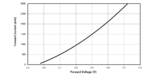
Hello everyone, I am working on SEPIC LED driver for my university project, I designed my LED driver in the simulation program. I used resistance as a load. I run it under PWM control by giving square waves from the signal generator. I get the output values I want in my simulation. Should I change the resistance value and duty value for LED dimming? I looked at the V-i characteristic graph from my LED catalog and entered the resistance value corresponding to the voltage-current values, calculated the new D value for the SEPIC converter according to the V value on V-i graph. When I enter the duty and resistance value in my simulation program, I cannot obtain the desired current and voltage value. I could not be sure whether my technique is wrong. This is my first experience with a Led driver, did I go the wrong way? I will be glad if you help
 

Attachments

  • V-i graph.PNG
    V-i graph.PNG
    28.4 KB · Views: 69

Hi,

A LED is far away from acting like a pure resistor. The V-I diagram surely shows this.

I'd use a zener with a series resistor for the simulation.

Klaus
 
Hi,

A LED is far away from acting like a pure resistor. The V-I diagram surely shows this.

I'd use a zener with a series resistor for the simulation.

Klaus

Are you talking about using zener with a series resistor instead of a load?

So I have to change the resistance value and duty ratio to simulate dimming again, right?
 

I am confused

You wrote you are working on a LED driver.
So the load should be a LED (or equivalent)
But then you wrote you used a resistor as load ... which is not a good equivalent.

Thus I recommended to use a zener with series R instead...as equivalent for the LED = load

I see no other option.
*****

Now you wrote:
I cannot obtain the desired current and voltage value. I
I don't see what you obtained, and I don't see what you desire.
Thus I'm unable to help with this

Klaus
 

I am confused

You wrote you are working on a LED driver.
So the load should be a LED (or equivalent)
But then you wrote you used a resistor as load ... which is not a good equivalent.

Thus I recommended to use a zener with series R instead...as equivalent for the LED = load

I see no other option.
*****

Now you wrote:
I don't see what you obtained, and I don't see what you desire.
Thus I'm unable to help with this

Klaus

I guess Icouldn't explain, sorry. I am working on an LED driver. Since the current of the LED I will use while simulating is 1A and its forward voltage is 3V, I used a 3 ohm resistor as a load. With the design I made, I achieved 3 V-1A output values. When I look at the LED V-i graph for dimming, I see that my output values should be 500mA at 2.7V and 1500mA at 2.9V. Considering that 2.7 = 500mA * R, I thought that the resistance I used as a load should be 5.4 ohms. Since the output voltage is 2.7, I thought that the new D value and R and the output values would give the 2.7V-500mA values given in the graph by recalculating the D ratio according to 2.7. But I could not get these values in the simulation.

I want to ask by which method how to examine how the circuit works at different loads in an LED driver simulation, is the path I applied wrong?[/QUOTE]
 
Last edited by a moderator:

Hi,

Wait...
The LED datasheet V-I-chart shows DC or instantaneous values.
But the PWM is ON/OFF. So the ideal values are 0A / 1A (for example)
So a 50% PWM it's half the time 0A and half the time 1A.
There ideally is no 0.5A.
You must not use PWM average values combined with the chart.

****
Another confusing thing:
You say you want to use a LED with 3V/1A, but the chart does not meet this.
I don't see how both informations match.

****
The V-I chart shows about 2.55V at zero current.
Then at 2.5A additional current it shows about 0.5V additional current.
So the dynamic resistance r = delta-V / delta-I = 0.5V / 2.5A = 0.2Ohms
So an ideal zener combined with a 0.2Ohms series resistance comes close to the V-I chart behaviour.

****

Still some confusion.
Please focus on one situation. One LED, the one you want to simulate.
And give all informations, sketches for this situation.

Klaus
 

Attached is a dimmable sepic for you in the free LTspice sim. Juts run it and watch.
Also you can change the current level in the led by changing the voltage into the external error amplifier.
 

Attachments

  • SEPIC _dimmable.zip
    1.4 KB · Views: 57

Status
Not open for further replies.

Similar threads

Part and Inventory Search

Welcome to EDABoard.com

Sponsor

Back
Top