Continue to Site

Welcome to EDAboard.com

Welcome to our site! EDAboard.com is an international Electronics Discussion Forum focused on EDA software, circuits, schematics, books, theory, papers, asic, pld, 8051, DSP, Network, RF, Analog Design, PCB, Service Manuals... and a whole lot more! To participate you need to register. Registration is free. Click here to register now.

IC recommendation for flyback constant current LED Driver in boundary conduction mode

Patrick_66

Member level 3
Joined
Nov 18, 2023
Messages
60
Helped
0
Reputation
0
Reaction score
0
Trophy points
6
Activity points
406
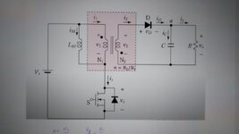
Hello everyone, can you guys give me some recommendations for the IC to provide a constant current LED driver for the flyback converter in boundary conduction mode? Mainly it is used for low power applications something like a constant current of 350 mA at the output even though i keep on increasing the load (adding more LED in series). Thank you in advance.
 
Using what In/out voltage range specs?
--- Updated ---

Not all LEDs have the same Rs , so you must define these LEDs to control current sharing or load regulation..
--- Updated ---

Boost or Buck
 
Last edited:
Sorry Sir I currently don't have much knowledge on this yet maybe can you give me an example of the input and output voltage range as for the LED it is a (3.5/350mA) LED. Can the system be a flyback converter in boundary conduction mode, can LT3798 or LT3799 be used as the current control system?
 
This buck-boost converter (simulation) steps voltage up or down to drive any desired number of led's, with the same peak Ampere level. It's controlled by 2 transistors.

Carefully adjust the lefthand potentiometer so that supply voltage turns the transistors on. The coil ramps up current producing voltage which opposes the bias voltage. The transistors shut off. The coil discharges through the load until levels fall to zero.

2-transistosr buck-boost 6V to desired amount of led's.png
 
This buck-boost converter (simulation) steps voltage up or down to drive any desired number of led's, with the same peak Ampere level. It's controlled by 2 transistors.

Carefully adjust the lefthand potentiometer so that supply voltage turns the transistors on. The coil ramps up current producing voltage which opposes the bias voltage. The transistors shut off. The coil discharges through the load until levels fall to zero.

View attachment 186536
5 mH is rather large for resistance and voltage drop. and when saturating PNP, change hFE to 10 or 20 unless you can control Vce>=1~2V
https://www.digikey.ca/en/products/detail/würth-elektronik/7447709152/3476692 Include URL to sim. pls. in future.
 
Link to Falstad's website and my schematic (post #4).
It loads and runs in the animated interactive simulator:

tinyurl.com/yvq3wupe

Click toggle Full Screen (under File menu).

Use mouse to move ground icon between various led's and change how many are included in the load.

Coil value can be changed by moving scroll wheel.
 
This buck-boost converter (simulation) steps voltage up or down to drive any desired number of led's, with the same peak Ampere level. It's controlled by 2 transistors.

Carefully adjust the lefthand potentiometer so that supply voltage turns the transistors on. The coil ramps up current producing voltage which opposes the bias voltage. The transistors shut off. The coil discharges through the load until levels fall to zero.

View attachment 186536
.LEDs need CCM not DCM or BCM< at rated currents.

Rate currents are >50% absolute max so 15% duty cycles like 350 mA for 1W LEDs or 20 mA avg for 75 mW 5mm at low duty cycles will exceed specs for abs max. current. So max/rms @ rated max current must be < 2 typ or as per the datasheet. and often 1.5 max. This imposes limits to muxing LEDs and DCM or BCM regulators.

No problem dimming if the duty cycle is near max at rated current or in CM CC mode.

But 15% d.c. at 350mA means 2.3A pk is too high.

The reason is in order to make the gold wire bond less visible on the anode, it imposes absolute max currents that limit this ratio. Otherwise it becomes a fuse.
Sorry for my ignorance. I think for now I need to learn the basics of simulating a flyback converter. Can you help me with that instead? What are the equations used to get all the necessary values to construct a flyback converter? As of now the question that I know of is as stated in the figure below but based on all the YouTube videos I watched some use different equations which is why I got confused. Can you help me? Let's say my input is 100 Vdc and output is 40 Vdc and the power is 100 W at 100 kHz. Can you simulate the circuit using LTspice? Sorry for asking so many questions. Thank you for all your help so far. Very much appreciate it, Sir. One more thing, will the equation be totally different if i want the system to be in BCM mode ?
 

Attachments

  • 1.jpeg
    1.jpeg
    36.1 KB · Views: 42
  • 3.jpeg
    3.jpeg
    32.4 KB · Views: 37
Last edited:
Last edited:

LaTeX Commands Quick-Menu:

Part and Inventory Search

Welcome to EDABoard.com

Sponsor

Back
Top