Continue to Site

Welcome to EDAboard.com

Welcome to our site! EDAboard.com is an international Electronics Discussion Forum focused on EDA software, circuits, schematics, books, theory, papers, asic, pld, 8051, DSP, Network, RF, Analog Design, PCB, Service Manuals... and a whole lot more! To participate you need to register. Registration is free. Click here to register now.

[SOLVED] LDO Voltage regulator getting hot - why?

Status
Not open for further replies.

GH Crash

Member level 1
Joined
Aug 5, 2022
Messages
41
Helped
0
Reputation
0
Reaction score
2
Trophy points
8
Activity points
507
I need some help in determining what is causing the voltage regulator to get hot in a simple circuit. Can you give me some ideas of how to find out what is causing the problem? Or, how to fix the problem?

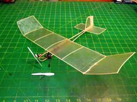
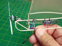
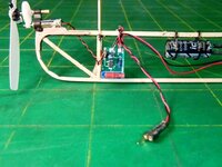
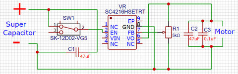
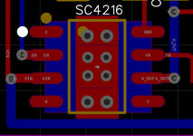
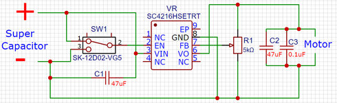
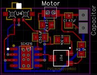
The circuit consists of a super capacitor, acting as the source, a variable output LDO voltage regulator, and a small DC motor. The voltage regulator chip is Semtech's SC4216HSETRT. It is rated for input voltages from 1.4 to 7 volts and current flow up to 3 amps. The super capacitor is rated at 7.5F at 5.4 volts. The motor is a brushed 7mm by 20mm coreless DC motor rated for 3.7 volts. The motor draws less than 1.5 amps at 3.7v under load. Capacitors have been added to the circuit as suggested by the SC4216 datasheet. A diagram of the circuit is attached. (It is almost exactly like the typical application circuit shown in the SC4216H data sheet.)

Prior to a test run, the voltage regulator's output voltage is set to 2.0 volts using a voltmeter and a separate bench-top power supply. The super capacitor is charged, using an external charger, to 4.0 volts prior to start of the test. The problem is that the voltage regulator chip gets too hot to touch within about 2 to 3 seconds of energizing the circuit.

I've added a second heat dissipation pad to the back of the PCB boards. Through board solder paths exists to tie the bottom pad to the surface pad. This didn't have appreciable effect other slightly the time interval before the IC was too hot to touch.

I've tried changing output voltage settings. Although it seemed the the voltage regulator IC took a little longer to heat up at higher output voltage settings, changing the output voltage didn't have an appreciable effects.

I've checked the voltage of the capacitor and it drops less than 0.2 volts under load.

I don't have a scope.

Can you help me to determine what is going on? And how to fix it? What is the cause of the excessive heating? I know that there will be some heat generated during normal operation but I can't understand why the chip gets so hot when it is operation in the middle of it designed operating range?

I'm sure that I have failed to mention something. Please feel free to ask question.

George
 

Attachments

  • SC4216 Basic.jpg
    SC4216 Basic.jpg
    93.3 KB · Views: 199

All there is, is power in and power out. V*I in. (Vin-Vout)*I out. Temp rise and thermal-impedance-to-universe takes the rest and there's the question.

2W in a small outline package with no heat sink and little board conduction is gonna get hot.
 

what is Vin (pin 3) of the SC4216 connected to?
how much current does the motor draw when running?

the switch to the enable pin does nothing. per the spec sheet, pin 2 open enables the regulator, as does tie-ing it to Vin.

The capacitor is charged to 4V and the output set to 2V, so the voltage drop across the regulator is 2V
multiply that by the current draw and you have the power is must dissipate.
The thermal resistance is 36 degC/W, case to ambient

2 W of dissipation (1 A current draw) means 72 deg C temperature rise, over ambient, which is probably about 20 deg C
so you regulator is getting up to almost 100 deg C - too hot to touch.

if your motor draws more current, the regulator is getting hotter.


are you sinking the device through the bottom, per thermal pad line on pin descriptions chart?
is pin 8 connected to the exposed die pad, per the pin descriptions chart?
this makes the thermal resistance 5 degC /W - much better

if you use a standard power supply instead of the super capacitor, how does the regulator behave?

i have not used a super capacitor, but i recall that when they first appeared on the market, they had large seres resistance and were really only good for holding volatile memory.
what is the ESR of your super capacitor?

I've added a second heat dissipation pad to the back of the PCB boards. Through board solder paths exists to tie the bottom pad to the surface pad.
i don't follow this
 

2W in a small outline package with no heat sink and little board conduction is gonna get hot.
Shouldn't the thermal pads dissipate that heat? I saw the thermal information in the datasheet but did not interoperate that to mean additional heat sink was needed.

I'm aware that the IC is going to warm up some but I was not expecting it to heat up as much as it is.
 

Even if a linear regulator is unstable, the dissipated power is still (Vin-Vout)*Iout.

Can you give us an idea of the effective PCB area acting as heatsink?
 

what is Vin (pin 3) of the SC4216 connected to? Oops. Pin3, Vin, is connected to the positive of the capacitor.
how much current does the motor draw when running? The motor draws 0.9a at 2.0 volts.

the switch to the enable pin does nothing. per the spec sheet, pin 2 open enables the regulator, as does tie-ing it to Vin. I don't understand. I think my drawing is confusing you. The switch ties the En pin into the capacitor positive when it is in one position. In the other position EN floats, isn't tied to anything. (the drawing should have a line from switch pin3 to negative.)
are you sinking the device through the bottom, per thermal pad line on pin descriptions chart? The exposed die pad on the bottom of the IC is soldered to an exposed copper pad on the PCB. There is a corresponded, but larger, exposed copper pad on the bottom of the board. These two pads are tied together by 8 vias with enlarged diameters so that solder wicks to the bottom board. These thermalpads are electrically isolated from the circuit at present. The attached board layout drawing illustrates the thermal pads. Traces and pads in red on top and bottom pads and traces are in blue.
is pin 8 connected to the exposed die pad, per the pin descriptions chart? No. It is tied to ground, to capacitor negative. Should it be?
this makes the thermal resistance 5 degC /W - much better Can you explain how it does that?

if you use a standard power supply instead of the super capacitor, how does the regulator behave? The chip acts exactly the same regardless of the power supply. I've tried it with LIC, EDLC, and bench-top power supply.

i have not used a super capacitor, but i recall that when they first appeared on the market, they had large seres resistance and were really only good for holding volatile memory.
what is the ESR of your super capacitor? 250 milliohms for the LIC. 55mOhms for the EDLC.


I hope my comments answer your questions. I really appreciate your input.
George
 

Attachments

  • Thermal Pads.jpg
    Thermal Pads.jpg
    57.7 KB · Views: 139

Even if a linear regulator is unstable, the dissipated power is still (Vin-Vout)*Iout.

Can you give us an idea of the effective PCB area acting as heatsink?

Is that true if its driving a C load ? Which it is.

Crude sim of oscillation :

1661466722343.png


Regards, Dana.
 
Last edited:

You have no schematic, no design specs , no component specs , excessive regulator electrical and thermal resistance and your results are to be expected from this design, which is very inappropriate.


My search found your motor may have these specs.

1661468915142.png

  • Voltage: DC 3.7V, Current: 0.1A
  • Speed: 45000 RPM
  • Motor diameter: 7MM, Motor length: 20MM
  • Output shaft diameter: 1MM, Output shaft length: 5MM
The current provided seems to be the no-load current so I expect rated-max. load to be 10x and start-surge up to 100x this current. You can verify by measuring the DC resistance which I expect in the 50 to 100 mohm range.

The appropriate solution used is a Lithium Ion battery which is about 10,000 Farads with an ESR < 75 mOhms and a suitable half bridge electronic speed controller (ESC) if you want variable speed.

Normally you want a regulator of any kind to have an ESR to be << 10% of the DCR of the load, to lose <, 10% of the total heat. but the surface area must spread the heat to minimize the temperature rise.

The reason linear regulators are inappropriate is the voltage drop over current is the effective resistance is too high (R=deltaV/I) and power (deltaV * I) loss is too great. The minimum dropout. of 300 mV (max) @ 1A. is good for a small LDO but poor for motor speed control. Of course, when the regulator voltage drop increases from input to output, the power loss just increases.

Whereas an ESC it uses very low resistance FET switches with no crossover current. The low side is switched with PWM to regulate the average DC voltage and no large capacitance is used on the output of fast switching ESC regulators.

Conclusion
- scrap the design , and just use a battery with ESC
 
Last edited:

wwfeldman said:
is pin 8 connected to the exposed die pad, per the pin descriptions chart? No. It is tied to ground, to capacitor negative. Should it be?

according to pin description table on page 6, pin 8 "Reference ground. The GND pin and the exposed die pad must be connected together at the IC pin."
so, yes

this line however, i misread the spec sheet - this is junction to case, not junction to ambient
this makes the thermal resistance 5 degC /W - much better Can you explain how it does that?

note page 3 of the SC4216 spec , note 2:
(2) Calculated from package in still air, mounted to 3 x 4.5 (in.), 4 layer FR4 PCB with thermal vias under the exposed pad per JESD51 standards.

it is unclear, but usually this means that it expects the heat sink to be 3 by 4.5 inches
since it is tied to ground, (pin 8), this implies that it expects the entire solder side (bottom layer)
to be a copper pour tied to ground to help dissipate the heat -
can you add a heat sink and a fan on the back side?
 

You have no schematic, no design specs , no component specs , excessive regulator electrical and thermal resistance and your results are to be expected from this design, which is very inappropriate.


My search found your motor may have these specs.

View attachment 178197
  • Voltage: DC 3.7V, Current: 0.1A
  • Speed: 45000 RPM
  • Motor diameter: 7MM, Motor length: 20MM
  • Output shaft diameter: 1MM, Output shaft length: 5MM
The current provided seems to be the no-load current so I expect rated-max. load to be 10x and start-surge up to 100x this current. You can verify by measuring the DC resistance which I expect in the 50 to 100 mohm range.

The appropriate solution used is a Lithium Ion battery which is about 10,000 Farads with an ESR < 75 mOhms and a suitable half bridge electronic speed controller (ESC) if you want variable speed.

Normally you want a regulator of any kind to have an ESR to be << 10% of the DCR of the load, to lose <, 10% of the total heat. but the surface area must spread the heat to minimize the temperature rise.

The reason linear regulators are inappropriate is the voltage drop over current is the effective resistance is too high (R=deltaV/I) and power (deltaV * I) loss is too great. The minimum dropout. of 300 mV (max) @ 1A. is good for a small LDO but poor for motor speed control. Of course, when the regulator voltage drop increases from input to output, the power loss just increases.

Whereas an ESC it uses very low resistance FET switches with no crossover current. The low side is switched with PWM to regulate the average DC voltage and no large capacitance is used on the output of fast switching ESC regulators.

Conclusion
- scrap the design , and just use a battery with ESC
Hi Tony,

Inappropriate: On what basis to you say the design is inappropriate? Can you provide a more appropriate circuit for controlling a small DC motor? The circuit needs to fix within a 1in x 1in area and weigh less than 0.75 grams.

No Schematic:
My schematic was attached to my first post? Do you want something else?
No design specs: The only electronic design spec for the circuit is to be able to control voltage to a DC motor. The power source will be a EDLC or LIC capacitor. The voltage and capacitance of the capacitor will vary from one application to another of the circuit.
No Component specs: I would have attached the datasheet for the one IC component but I have been told that isn't allowed on this forum. I supplied you with the manufacture's part number so that you could access the datasheet of you wished. Surely you don't need specs for a SPDT switch or a 5K trimming pot.
Motor: The motor you found is one possibilities for the load. There are several motors of that type (DC coreless) that may/might be used. They very in diameter, length and internal resistance. As with the capacitor, the motor used will vary depending upon the application.

Use Battery: The purpose of the circuit is to provide some degree of motor speed control when using a super capacitor as the power source.

Voltage regulator/ ESC: I don't think that I fully understand you said about a regulator. I built a similar circuit that used a LDO VR rated at 0.4 amps. It worked well as a throttle on a 6mm motor drawing 0,5 amps. It also gave me a very flat voltage curve when the capacitor voltage was above the output voltage setting without any heating. I do know that the voltage regulator is inefficient. But, right now, it seems to be the best approach. The use of PWM would be more efficient but pulse width would have to be adjusted continually as the capacitor voltage drops. I am unaware of a PWM circuit that self adjusts the pulse width so that the output power remains constant. Please let me know if you are aware of a self adjusting ESC circuit design.

You said "Scrap the design and just use a battery with ESC." What is the fun it that?

George
 

Hi,
No Component specs: I would have attached the datasheet for the one IC component but I have been told that isn't allowed on this forum
Who told you this? In what context?
In this forum you will see a lot of attached datasheets.
But the recommendation is to post a link to the datasheet on the manufacturer´s site.

Generally I tend to agree with Tony.
* Schematic: It is wrong (missing connection) and misses informations about power sourcce, load and component informations. One has to read a lot through the thread to find out some things. ther are different types of capacitors for example. Thus 10uF electrolytics is for different applications than 10uF of ceramics.

* the provided PCB layout is the minimum snippet that just shows the IC, no capacitors no trace lengths, no GND plane, no heat sink. The blue copper area in size is far from "mounted to 3 x 4.5 (in.), 4 layer FR4 PCB".

A voltage regulator is designed to generate a stable DC voltage mainly to supply semiconductor devices. In your case it supplies a motor with extremely noisy current draw (compared to semiconductors) and a variable ouput voltage. It is likely that it goes out of control with the dynamic motor current, especially when you turn the voltage down, and it may have problems handling the back EMV of the motor. ( there may be a lot of rotation energy of the motor going backwards the regulator)
Using capacitors in parallel to (inductive) motors may lead to resonances.

Usually one could use a dedicated motor controller chip, or use PWM for motor speed control. There even are ready to buy motor controller modules.

Klaus
 

Klaus and Tony, you two are pretty rough on a guy who is trying to learn how to communicate in a area (electronics) where he has very little experience and even less knowledge.

Yes, the drawing/schematic had errors I missed before posting. Sorry about that. Attached is a corrected one. For the purpose of this problem solving let us assume that all capacitors < 50uF are ceramic.

The snippet was meant to show the size and layout of the heat sink pads on the board. The posting did not say anything about the entire board layout. The posting did say "The attached board layout drawing illustrates the thermal pads. Traces and pads in red on top and bottom pads and traces are in blue." And, if the board layout is that important, why wasn't ask for? Here is the complete board. Grid sizeis 25mm by 2.5mm. The open area below U2, the switch, is reserved for a low voltage protection chip.


I think that the problem is that there just isn't enough heat sink. Three of the responder mentioned the note concerning how Thermal Resistance was derived. Note 2 said "calculated from package in still air mounted to a 3 x 4.5 (in)......exposed pad," I read that note as information on how thermal resistance was calculated not as the size of thermal pad needed. Several responses have mention that note and implied that I needed a bigger pad.

Do you agree that additional heat sink area is needed? How do I calculate (where do I finds he formula?) how much area is needed?
 

Attachments

  • 3a CVR Circuit.jpg
    3a CVR Circuit.jpg
    136.2 KB · Views: 145
  • CVR Board 8-17 AM.jpg
    CVR Board 8-17 AM.jpg
    157 KB · Views: 157

Hi,
Klaus and Tony, you two are pretty rough on a guy who is trying to learn
I´m a German, and we Germans are known not to sugarcoat when discussing technical problems.
We focus on the technical issues and how to solve them effectively in a short time.
A can assure that this behavior is not intended to offend you personally.

When I ask for complete information, I don't do it to annoy or bother you, but to get a clear view of your situation... to provide you with the best help in a short amount of time.

It´s totally O.K. for me if you don´t want me respond.

Klaus
 
You are in a place where the problem is defined external to the chip. The thermal interplay of board area, planes' thermal impedance from that area (and how much of it) to air, and the airflow needed to take 2W "elsewhere".

This all probably resides at PCB mfrs' tech pages or third parties engaged at PCB design.

Failing any better advice, go with "mobetta" on airflow and area of thermally-connected planes in/on the board. Designed-in things like thermal vias and choosing an outer layer to take the heat flux are part of the art.
 

Hi,

I´m a German, and we Germans are known not to sugarcoat when discussing technical problems.
We focus on the technical issues and how to solve them effectively in a short time.
A can assure that this behavior is not intended to offend you personally.

When I ask for complete information, I don't do it to annoy or bother you, but to get a clear view of your situation... to provide you with the best help in a short amount of time.

It´s totally O.K. for me if you don´t want me respond.

Klaus
I Figured that you were German. I like Germans, good folks all around. If they have a fault, it is that they are sometimes a little over serious.

I don't take anything personally, but that doesn't stop me from complaining a little. Complete information is a necessity in problem solving. I try to supply all the information. Unfortunately I don't always know what information is needed. Please ask for the information you need and I will try to supple it. Just don't complain about missing information when that information has not been requested. Remember, I'm just an uneducated when it comes to electronics, I don't always know what information is needed or the best way to convey that information.

Above all, continue to respond. I value your responses. I may act like, or sometimes feel like, the response isn't pertinent to the problem but there is something to learn in almost everyone of your responses, in almost every responses, regardless of who posts the response.

Do you agree that additional heat sink area is needed?

Because of dimensional requirements (< 4 cm^2 PCB area), it may not be possible to add sufficient heat sink area. In such a case, what other approaches are there that might be used to provide constant power output with a decreasing input voltage? Several individuals have suggested that a PWM based approach but I am unaware of a self regulating PWM circuit or IC? (I'm not asking for a specific IC or circuit design. I'm asking if anyone knows of such and if they are willing to direct me to where to go to learn learn more).

George
 

Hi,

Maybe a starting point (or not) to look into a PWM version of your circuit, even if you will stick with the LDO, could be (because there are lots of examples) is an astable 555 driving a mosfet that can cope with the motor, and using an op amp configuration of an appropriate type as the sensing device that provides the feedback to the 555 control pin. If it's the motor current you need to control, a current sense amplifier or difference amplifier around a sensing resistor in line with the motor that feeds a rudimentary error amplifier with it's reference voltage scaled to the desired current would be the 555 control pin input. A ground-referenced sensing resistor between motor and ground would dispense with diff amp/CSA, like a typical op amp current source circuit (Iout = Vref/Rsense). Tiny milliohm resistor that doesn't steal too much voltage and adding gain if needed using non-inverting amplifier.

Not sure how clunky that would be when rowdy motor turns on and off. Presumably MOSFET would need snubber. And is more parts than an LDO.

Read inadvertently hysterical document other day about suitable heat-sinking are for a SOIC IC was 10cm2 - about the size of an entire PCB almost, some transistor datasheets are equally 'read the small print', i.e."see note (1)", etc., where PD of 2W is for huge copper area under IC, normal-sized landing pad is 2/5 that '2W' amount of PD... It does show importance/utility of getting heat out of parts, though, especially if you plan to touch them ;).
 

Hi,

All linear reglators have the same problem: all dissipate the same power ... no matter if this us dissipated in Rs, Mosfets, BJTs..

If you want to reduce dissipated power you need to use switched solutions.
I recommend to use dedicated motor control solutions.

You talk about "self regulated PWM" ... that's basically what most SMPS do.
In your case: a non isolated buck converter with up to 100% duty cycle.
It provides rather clean DC output ... which you don't need for motor control. Thus a motor control may be cheaper.

But usually it's not the target to provide a motor with a dedicated DC voltage .... usually the target is to control RPM, or torque or....
Here also dedicated motor control may provide special features.. for example RPM control...or what ever your application is after..

Klaus
 

Klaus and a123,
I appreciate you point out possible solution to the heating problem. Unfortunately I need a little more assistance. First, let me state that the ultimate goal to to control the motor's power. How that is done is immaterial. I chose to try and control motor voltage since that seemed the simplest approach realizing that it was a energy wasting approach.. As far as I'm concerned any and all methods of controlling a small DC motor power are worthy of consideration.

There are two physical restraints that need to be remembered, circuit footprint and circuit weight. I have failed to emphasize these constraints because the original voltage regulator circuit met those requirement. . The complete motor control circuit should have a footprint as small as possible. For those of you who need exact specs, that means the entire circuit should fit on a PCB no larger that 1in^2 (6.5cm^2). The complete control circuit should be as light as possible. In this case, the heavier the circuit the less useful it becomes. For those addicted to hard numbers, a total weight over 1.5 gram is unacceptable, a weight under 0.75g is desirable..

a123
I'm not familiar with a 555. Can you provide more details about what a 555 is? Is there a web site or paper the would help me understand?

Klaus, I assume that SMPS is an acronym for something. What does SMPS stand for?

I will investigate both the 555 and SMPS just give me some time.

And just an FYI for you. The attached photos show a indoor capacitor powered electric free flight model that has a voltage regulator motor control. The plane with a 3F capacitor and the controller weighs 5.5 grams. Without the the volt regulator flight times were in the two minute range, with the controller flight times were almost doubled. The problem with the LDO voltage regulator used is that it is rated for 0.4 amps max.
 

Attachments

  • 004.JPG
    004.JPG
    1.7 MB · Views: 149
  • 008.JPG
    008.JPG
    200.2 KB · Views: 141
  • 012.JPG
    012.JPG
    223.1 KB · Views: 148

I buy Micro Ready to Fly radio controlled model airplanes at my local hobby store. They are made by E-flite and their main USA distributor is Horizon Hobby.

The coreless brushed motors are cheap and have a very short life. They were originally used to occasionally open and close a CD tray or occasionally operate a vibrator in a phone. The brushes wear out or burn out soon when running continuously on a model airplane or toy helicopter/drone.
The "beginners" RC airplanes use a single-cell Li-Po battery that charges to 4.2V, averages 3.7V during a discharge and the driver circuit disconnects the main motor when the battery voltage drops to 3.0V (leaving the receiver and servos working). The cheap motors need gears.

Brushless motors powered from one or two Li-Po cells are available in model airplanes used by skilled users. They do nor burn out or wear out and "last forever".
PWM is used to control motor speed with barely any losses or heating. The brushless motors produce lots of torque and do not use gears.
 

Status
Not open for further replies.

Part and Inventory Search

Welcome to EDABoard.com

Sponsor

Back
Top