amintlk
Member level 1
hi to all
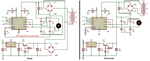
i made a driver with l298 and it work well , i parallel two channel ... my motor was 24v 300mA .. but recently i made another one just like last one ,but in new one my l298 get very hot .. the motors are same ... i have both of them now , in older one my l298 work without heating and in new one l298 get very hot and after a few second breakdown .. even if i use without load the l298 get very hot .. i've changed a lot of l298 ...
i made a driver with l298 and it work well , i parallel two channel ... my motor was 24v 300mA .. but recently i made another one just like last one ,but in new one my l298 get very hot .. the motors are same ... i have both of them now , in older one my l298 work without heating and in new one l298 get very hot and after a few second breakdown .. even if i use without load the l298 get very hot .. i've changed a lot of l298 ...