Continue to Site

Welcome to EDAboard.com

Welcome to our site! EDAboard.com is an international Electronics Discussion Forum focused on EDA software, circuits, schematics, books, theory, papers, asic, pld, 8051, DSP, Network, RF, Analog Design, PCB, Service Manuals... and a whole lot more! To participate you need to register. Registration is free. Click here to register now.

L298 DC motor control

Status
Not open for further replies.

HAIDE

Junior Member level 3
Joined
Feb 9, 2012
Messages
27
Helped
0
Reputation
0
Reaction score
0
Trophy points
1,281
Location
GERMANY
Activity points
1,525
Hi,
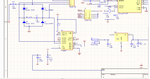
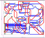
I design a circuit by DC motor, which controlled by micro controller(using PWM), I want to control a 24 volt dc motor by L298, I have designed a schematic file but I'm not sure this is works, I atached the both schematcs in pdf and a part of circuit in image and also PCB, any idea?:idea:
Also another question is L298 is proper choice to control 24 volt DC motor?
 

Attachments

  • ALI200.png
    ALI200.png
    50 KB · Views: 155
  • ALI300.png
    ALI300.png
    57.7 KB · Views: 126
  • ali500.pdf
    55.3 KB · Views: 113

There are several concerns about your schematic --

1) your ISens pins are useful if you want to measure the motor current in a full bridge config - i.e. using 2x of the L298 drivers. Otherwise it should go to GND directly. You have used a 1K in series which will severly limit the operation.

2) your full schematic is not visible (oh - i see the full schematic in your .pdf!!) I see that you have 4x diodes connected. This implies that you want to run your motor in both directions. However your IN1 and IN2 are hard-wired for only one direction. You need to decide whether you want single-direction or both-direction control, and make mods accordingly. As of now OUT2 will go hi, OUT1 go low when EN-A is high, and go tri-state with EN-A low - 'Free-running motor stop' condition. If you want 2-direction, then you should control IN1 & IN2 as well.

3) The ENA/B pins control pairs of half-bridges. A PWM fed to this is fine. You should ground EN-B - since you are not using OUT3 & OUT4

4) A 100nF is recommended on Vss pin.

5) your motor is working on +5v. A 24v motor might not even begin to turn with this low voltage. Or turn very slowly even at max PWM duty cycle. Some 'heavier' motors need a minimum voltage to start them going.

6) What sort of motor are you driving with this ? the L298 can handle 46v, and >2amps per channel. Its OK to use L298, but be sure you are within these ratings. At the higher current levels it'll get hot (it has an internal voltage-drop, so effiency is not that great). Plan for a heatsink/ fan if a higher current is required.
 
Last edited:
Dear Rohitkhanna, thanks for your help, but one question, what is the difference of using L298 in 24V DC motor in comparison with 12V I suppose the difference is only Vs pin is it correct? and is it true using resistor in ISens pins to avoiding current more than 2A.
 

Dear Rohitkhanna, thanks for your help, but one question, what is the difference of using L298 in 24V DC motor in comparison with 12V I suppose the difference is only Vs pin is it correct? and is it true using resistor in ISens pins to avoiding current more than 2A.

Yes - the voltage at Vs pin is the max voltage to the motor (actually a bit less) - in full bridge config. in half-bridge the motor's other end could be connected to some other voltage.

The resistor on Isens does NOT "control" the current. It just acts like a current-to-voltage ( V = IxR) converter so that your uC/ Opamp/ ADC/ whatever can then "sense" it and take action accordingly. This resistor - if used - would normally be very small. Definitely less than 1 ohm i think. Any 'control' of the motor currents would normally then be achieved by adjusting the PWM duty cycle based on this sensed voltage.

Lastly - where exactly is this 12v you keep writing about ? I do not see it anywhere on your schematic. Ah!!! i see it now - it is the unmarked input power jack!
You need to put in bigger caps here - several 100's of uF at least - not just 100pF.

Also your free-wheeling diodes should be returned to this same '+12v' and not to the +5v Vcc as you have done. You will short your power supplies & your L298 through D2 !!
 
  • Like
Reactions: HAIDE

    HAIDE

    Points: 2
    Helpful Answer Positive Rating
Dear Rohitkhanna,Thank you for your help, I did what you specified , and I attached the fixed schematic, Do you think it works?
 

Attachments

  • PCB-H.pdf
    56.7 KB · Views: 115

Much better now. You will have full control of L298 speed & direction with this.

A few other points I noticed --

1) make sure the high current tracks on your PCB are wide enough to carry the higher current. (what IS the motor spec's - you have still not specified)
2) you don't really need C11, C12, R9. Maybe later if you have trouble with ringing/ oscillations
3) The LCD backlight is usually just like a normal LED, so if you want to control that, you could drive it directly from uC pin with a 470ohm in series. As it is not, your LED/ Q1 will probably blow.
4) Your reset circuit is slightly unusual - though it looks like it will work too.
5) Pin3 on LCD header is used for LCD contrast setting. It should typically have a potentiometer connected to allow contrast adjustment. I have never seen a diode used here.
6) you don't really need a 2nd 7805 just to drive the LCD - just use the common Vcc. interesting to observe that BOTH your 7805's are labeled U2 !!
7) ideally you should put in a series resistor on input of your 7805 - you are dropping ( 24 - 5 = ) 19volts here! So even a 100mA load will cause the 7805 to dissipate 1.9watts - its typical rated power without heatsink. I suggest you plan for a heatsink, and plan for a series resistor here of around 2W size. Until we know what the circuit load is, can't say much more...
8) Since I do not think you will be needing extreme high timing precision, you can also eliminate the crystal, and just use the Internal RC oscillator set for the same 8MHz.
9) I assume you will remember to enable the pull-up resistors on the port pins PC0..3, otherwise your keys will have no effect. Also implement some software debounce. Putting in a small cap (~1nf - 10nF) across each key will help in the debounce issue.
10) on the uC, Vcc, AVcc, Aref can all be shorted and tied directly to your VCC line, with a single 100nF to ground. Usually you will not need the L1. I don't think you are using ADC or even AIN, so all this is not required.

And lastly - in case you want to later also monitor the motor current - you can leave provision to connect a low-ohm ~3w-5w resistor between Isens and ground. Then connect Isens also to AIN1 of the uC. You have to use AIN1 since all the ADC pins are already used up. Then you could plan to sense an over-current situation by using the Analog Comparator function, where you set AIN0 to be Bandgap Reference (~ 1.23v). So suppose you want to detect if motor current is >2 amps. Then you choose the resistor to be ( 1.23v/ 2A = ) 0.615 ohms. This does NOT limit the current by itself, it only allows the uc to know if current is >2A and take corrective action if required.

thats it for now...
cheers!
 
  • Like
Reactions: HAIDE

    HAIDE

    Points: 2
    Helpful Answer Positive Rating
Dear Rohitkhanna, thank you for your valuable points, I am using Buhler DC motor 24 volt, 400 PPM
Manufacturer: Buhler Motor
Speed: 3000 RPM
Torque: 5 Ncm
Current: 1.5 A
any thing I have to do with my schematic?
 

Status
Not open for further replies.

Part and Inventory Search

Welcome to EDABoard.com

Sponsor

Back
Top