Continue to Site

Welcome to EDAboard.com

Welcome to our site! EDAboard.com is an international Electronics Discussion Forum focused on EDA software, circuits, schematics, books, theory, papers, asic, pld, 8051, DSP, Network, RF, Analog Design, PCB, Service Manuals... and a whole lot more! To participate you need to register. Registration is free. Click here to register now.

Keurig button PCB scratched trace, easy to remake circuit? + How to wire relay?

Status
Not open for further replies.

nullsec

Newbie
Joined
Sep 13, 2020
Messages
2
Helped
0
Reputation
0
Reaction score
0
Trophy points
1
Activity points
45
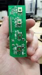
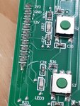
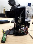
Was disassembling my Keurig K-Compact K35 and I accidentally scratched the PCB with the buttons.

Intention of disassembly was to wire in a few relays to allow control of the buttons with a Raspberry PI.

Would it be easier (if at all possible) to remake the circuit on a breadboard for now so I can get my RPI project going or should I just try to bridge the trace?

I'm also wondering how one would figure out how to wire the relays into this, and how one would identify what signals are sent when the buttons are pressed. I was not thinking the buttons PCB would be so complicated. Not sure how I would wire a relay into this, even if the PCB was not scratched.

New to electronics, not experienced soldering, and have very unsteady hands. Let me know what additional information I can provide.

Any and all help appreciated.
 

Attachments

  • keurig_compact_k35_button_pcb.jpg
    keurig_compact_k35_button_pcb.jpg
    123.9 KB · Views: 199
  • keurig_compact_k35_scratch_closer.jpg
    keurig_compact_k35_scratch_closer.jpg
    284.7 KB · Views: 198
  • keurig_compact_k35_full_view.jpg
    keurig_compact_k35_full_view.jpg
    222.4 KB · Views: 156

A coffee maker?

What you do depends very much on what is on the other side of the PCB, if it only has switches and LEDs on it the other components shouldn't be there.
I would tackle the repair in one of two ways, either scratch off the green paint (solder resist) at each side of the damage then solder a wire bridge across the gap -or- use a fine insulated wire to bridge the broken connection but soldered to the start and end points of the track where there are bigger pads to connect to.

As for wiring relays, as long as you are not likely to press a button at the same time as operating a relay, wire the 'common' pin of the relay to one side of the actual switch on the board and the 'normally closed' pin to the other side of the switch. operating the relay will than have the same effect as pressing the switch. To drive a relay from a RPi, you will need a driver transistor to boost the available current from the Pi's output pin, a resistor to limit the current and a diode to go across the relay coil.

Brian.
 

Is this the gouge? It does not appear to sever a trace.

I would poke with a toothpick between the traces, while examining under a magnifying glass. Make sure no metal was pushed between the traces to create a conductive bridge. If it was then clear it away with the toothpick.

You must determine which contacts are joined by the pushbutton. A voltmeter can assist. When the button is up It shows voltage across the correct contacts. When you press the button, voltage drops to zero. It's probably also okay to use the ohmmeter function, although it's wise to use a high range because that sends less current out the leads.

closeup_gouge.png
 

Thank you for your help. It seems some metal was pushed between the traces.

I was also able to identify how to wire relays in to the circuit.
 

Good going! Now it sounds as though you'll have an easy time modifying your existing board, rather than try to remake the circuit anew.
 

Status
Not open for further replies.

Part and Inventory Search

Welcome to EDABoard.com

Sponsor

Back
Top