Continue to Site

Welcome to EDAboard.com

Welcome to our site! EDAboard.com is an international Electronics Discussion Forum focused on EDA software, circuits, schematics, books, theory, papers, asic, pld, 8051, DSP, Network, RF, Analog Design, PCB, Service Manuals... and a whole lot more! To participate you need to register. Registration is free. Click here to register now.

Is using Voltage Regulator for FPGA & MPU a good option ?

Status
Not open for further replies.

abdo.medo1000

Member level 1
Joined
Apr 27, 2021
Messages
33
Helped
0
Reputation
0
Reaction score
0
Trophy points
6
Activity points
324
Hi

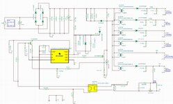
I have designed a switched mode power supply circuit using UCC28C42 IC, the circuit should work with wide range input of 40 -350 DC. The circuit have multiple outputs (24v, 10v, -10, 5v and 3.3v). I have manufactured and custom transformer with thesis parameters from local manufacturers.

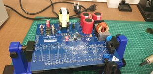
I have tested the whole circuit on TINA TI, and it is working very well with different voltage input from 40 DC till 350v DC, but when I made the PCB of the circuit and tested it on the lab.

The problem is the output of 5v and 3.3v are changing when the applied input voltage is low.

I have tested the circuit with these values:


Inputoutput of 3.3voutput of 5voutput of 10voutput of -10v
220 AC (after the bridge rectifiers is 310 DC)3.8v DC5.5v DC10.3v DC-10.8v DC
65v DC2.0v DC3.1v DC10v DC-10v DC
51v DC1.9v DC2.6v DC9.9v DC-10.5 DC
131 DC2.4v DC3.7v DC9.8v DC-10.5 DC


As you see on the table above when applying voltage lower than 300v the value of output 3.3v and 5v is decreasing but the voltage values of 10v and -10v seem stable.

Why this problem is happening, why some voltage outputs are decreasing, and the other are not ?


I will use 3.3v and 5v to feed my STM32 MP1 MPU, STM32f4 MCU and ARTIX 7 FPGA for that I want to have steady voltage for them what do you recommend for me as a solution?

Is using a Linear Voltage Regulator a good option?


I am looking forward for your answer
 

No schematic or Layout = no way to answer. About the only answer I can give you is ‘there’s something wrong’.
 

Hi,

first of all, we need more information.
Like:
* show your schematic. Especially how you did your feedback.
* show your test setup and conditions. Did you use a default load at the outputs while testing?
* how exactly is your transformer setup and winding.
* also show your PCB layout.

I guess this is a flyback setup. So you have one common feedback for all the output voltages. Now on no load (or very low load) conditionn you get non continous switching and noise and random looking spikes dominate the transformer output. You should check this with a scope. Due to diode capacitance and speed and also stray impedances the output voltage will vary a lot, ... errors and parasitics gain more influence than in loaded situation.

So you may do the tests again with minimum expectable load at each output to get more "realistic" results.

The flyback with multiple output is good for known load conditions. It has it´s drawback when the load at the outputs vary a lot.
So the - for me - better (more universal) solution is to just generate one output with the highest voltage and use this for the SMPS feedback. All other voltages can be generated by this voltage using non isolated buck converters. For sure a lot more effort and cost.

Especially when you want some kind of precision in the output voltages - for measurement purpose for example - then linear post regulators are a good idea.

So which solution is the best for you depends on your requirements .. which are completely unknown to us.

Klaus
 
No schematic or Layout = no way to answer. About the only answer I can give you is ‘there’s something wrong’.
Thank you for replying,

I have attached the schematic above, please check it.
--- Updated ---

Hi,

first of all, we need more information.
Like:
* show your schematic. Especially how you did your feedback.
* show your test setup and conditions. Did you use a default load at the outputs while testing?
* how exactly is your transformer setup and winding.
* also show your PCB layout.

I guess this is a flyback setup. So you have one common feedback for all the output voltages. Now on no load (or very low load) conditionn you get non continous switching and noise and random looking spikes dominate the transformer output. You should check this with a scope. Due to diode capacitance and speed and also stray impedances the output voltage will vary a lot, ... errors and parasitics gain more influence than in loaded situation.

So you may do the tests again with minimum expectable load at each output to get more "realistic" results.

The flyback with multiple output is good for known load conditions. It has it´s drawback when the load at the outputs vary a lot.
So the - for me - better (more universal) solution is to just generate one output with the highest voltage and use this for the SMPS feedback. All other voltages can be generated by this voltage using non isolated buck converters. For sure a lot more effort and cost.

Especially when you want some kind of precision in the output voltages - for measurement purpose for example - then linear post regulators are a good idea.

So which solution is the best for you depends on your requirements .. which are completely unknown to us.

Klaus
Thank you very much, Mr Klauss for your helpful answer,
I have attached the schematic above, please check it.
As you guessed yes I am using Flyback topology, and I am taking the feedback from the higher voltage which is 24v as shown on the PCB schematic below.

I already designed a custom flyback transformer for the circuit but the problem as I mentioned before is this circuit should work with wide input DC and AC from 40-350 DC.

And it works very well on only high voltage (when input voltage is 310 , all the outputs are very well as I waited) but when applying lower voltage the smallest voltage outputs (3.3v and 5v) are not steady.

You mentioned about using linear post regulators, are they the same with LDO Voltage Regulators ?

For example, is there are any regulator work like that below ?

The input will be any value from 1v to 5v and the output will be fixed 3.3v 1.3A
and 1v to 8v and the output will be fixed 5v 1.2A

if yes, what are they ?

[moderator action: removed copy of post#1]
 

Attachments

  • ucc28c42.jpg
    ucc28c42.jpg
    355.6 KB · Views: 126
  • powersupply.pdf
    102 KB · Views: 128
  • 20220826_201835.jpg
    20220826_201835.jpg
    2 MB · Views: 128
Last edited by a moderator:

Hi,

first things first.
I asked for more informations. You just showed the schematic. Indeed two different ones. Not clear which ist the one you want to discuss about.

(Btw: Don´t use JPG for screenshots. Use PNG for screenshots of diagrams, schematics and so on.
Use JPG for photos. Usually 100kB for a photo should be sufficient. about 1000 px in width and 35% quality)

Then please decide the expected min/max range for each of your outputs in numbers with units.

You mentioned about using linear post regulators, are they the same with LDO Voltage Regulators ?
An internet search provides a lot of information about this. More detailed than we can do in a forum thread. It´s a rather basic question, thus it´s expected that you do a research on your own.
If after that still questions exist, then you are welcome to ask them here.

Klaus
 
I would recommend trying to get regulation on the "5V"
supply, most of these older Unitrode parts are meant
for a 5V (or 5.1V) feedback reference so that's pretty
clean / normal.

Then you can use either a 5V-input POL DC-DC or a
low dropout linear regulator to get the 3.3V.

The +/-10V I'd let go as "cross-regulated" (windings)
but you might prefer to make these +/-15V and then
regulate them down, with regulators that can scrub
off the ripple and ringing of the switcher (7805, 7905
probably have too low a corner frequency to fully do
the job, Linear Tech has some with HF PSRR as a
selling-point). There are also folks selling little TO-220
form factor, switchers meant to drop into those 7805 /
7905 positions although they aren't going to be any
quieter, likely worse noise-wise.

Now if your goal is not simply the experience, but a
proper supply set with good tolerances & rejections,
there are many suppliers of multi-ouput "bricks" and
picking up a good-to-go +5, +/-15 one might save you
a lot of grief. Seeing as your simulations appear to
show no actual "regulation" whatsoever.
 
As far as I understand, there are not two different schematics, but a real designa and a simulation schematic. You should be able to see the observed effects (poor output tracking) in simulation if you add realistic transformer models with leakage inductance and optionally windings capacitance.
 

* show your schematic. Especially how you did your feedback.
I made my feedback as shown on the schematic below

[removed link]

* show your test setup and conditions. Did you use a default load at the outputs while testing?

What do you mean with test setup ? Do you mean how I test the PCB on the lab ?
I am sung the multimeter to measure the output voltage and oscilloscope to check all test points.


how exactly is your transformer setup and winding.
here is the datasheet of the transformer that the local manufacturer sent to me ,
[removed link]

* also show your PCB layout.

here are some pictures from the lab

[removed link]

and you can check also my PSC layout online from Allium Designer online viewer here

[removed link]


............................

As you mentioned above, I am getting correct output voltages under no load condition for all outputs. However, I am getting reduced voltages for all the outputs when I connect load (resistors in parallel).

How can I solve this problem, why the output voltages changes when I connect load, knowing that my transformer should work because they made it according to the specifications below,

This table below is what I sent to the Transformer manufacturer and according to it, they manufactured the transformer for me

Primary voltage rating40-350vOutput current
1st Secondary 3.3v1 A
2nd Secondary 5v0.8 A
3rd Secondary 10v0.8 A
4th Secondary 10v0.8 A
5th Auxiliary voltage rating Secondary 15v0.05
6th Secondary 24v0.4 A
Duty Cycle (Maximum)0.6
Switching Frequency115KHz

I am looking forward for your support

Thanks in advance.

[moderator action: removed links to external file servers]
 
Last edited by a moderator:

Hi,

As you mentioned above, I am getting correct output voltages under no load condition for all outputs. However, I am getting reduced voltages for all the outputs when I connect load (resistors in parallel).

How can I solve this problem, why the output voltages changes when I connect load, knowing that my transformer should work because they made it according to the specifications below,
Now you talk about a differnt problem.

Before you said the output voltage varies with input voltage.
Now you say the output voltage varies with load current.

Klaus
 

Hi,


Now you talk about a differnt problem.

Before you said the output voltage varies with input voltage.
Now you say the output voltage varies with load current.

Klaus
Yes , this is another problem happend when I added load on the outputs.
 

These both come back to a compete lack of regulation / loop closure (for whatever reason, finding which is job #1).
what do you mean by "lack of regulation / loop closure" ?
--- Updated ---

I made my feedback as shown on the schematic below
I attached the circuit schematic below.


here is the datasheet of the transformer that the local manufacturer sent to me ,
I attached also the datasheet of the transformer below
here are some pictures from the lab
R_PCB.jpg

PCB layout.png

3D layout.png


and I attached also PCB file (Allium Designer file) below
 

Attachments

  • PS_circuit schematic.pdf
    102 KB · Views: 114
  • Transformer SM 0281139.pdf
    335.3 KB · Views: 111
Last edited:

Feedback is connected to 24 V output (probably not the best idea, as already mentioned by contributors), lack of regulation means that 24 V output can't be maintained. Is it so?

My general expectations:
Don't expect sufficient voltage tracking for unloaded outputs or very asymmetric loads. Start test with typical load of all outputs and apply variations around this operation point.

Take a look at PC power supply schematics that have additional regulation means for individual outputs.
 
If you only regulate on one output - you cannot expect the other outputs to stay constant under line and load variation - this is power electronics 1.01

there is a lot of work in designing a psu that closely regulates all outputs at the same time - yours is not one of these.

Start from the basics my friend - your best bet to salvage this car crash is to have ONE isolated output at the highest rail voltage needed, and then buck converters to generate all the other required outputs ....
 
24 V output can't be maintained. Is it so?
Yes, even no load, the 24 output can not be maintained.

Don't expect sufficient voltage tracking for unloaded outputs or very asymmetric loads. Start test with typical load of all outputs and apply variations around this operation point.
Why ? Isn't the purpose of the feedback system to stabilize the system?
What do you mean with typical load ?
Take a look at PC power supply schematics that have additional regulation means for individual outputs.
Thank you for this advice, I looked to some schematics and I found all of them have feedback from all the outputs of the transformer. Should I do the same ? If yes, how can I add feedback for another outputs on my schematic?
--- Updated ---

you cannot expect the other outputs to stay constant under line and load variation
Why ? What is the problem with the circuit ?

there is a lot of work in designing a psu that closely regulates all outputs at the same time - yours is not one of these.
May you mention any of them please ? I checked this file from onsemi TND351, I saw that the feedback system there is like my circuit? Isn't like it ?

I already ordered all the components of this circuit and manufactured the transformer and made the PCB, according to that, wouldn't it be better if we solve the problem of the instability of the system?

Would make a new circuit with one output and regulate the 24v output with buck converters and LDO regulators be the best way to get this power supply work ?
 
Last edited:

Have you shown us the instability you mention - scope shots ? what loading? no information = no useful answers ...
--- Updated ---

R9 => 22 ohm

R13 => 1k5
R14 => 470 ohms
C22 => 47nF

for starters
 
Last edited:

Status
Not open for further replies.

Part and Inventory Search

Welcome to EDABoard.com

Sponsor

Back
Top