Continue to Site

Welcome to EDAboard.com

Welcome to our site! EDAboard.com is an international Electronics Discussion Forum focused on EDA software, circuits, schematics, books, theory, papers, asic, pld, 8051, DSP, Network, RF, Analog Design, PCB, Service Manuals... and a whole lot more! To participate you need to register. Registration is free. Click here to register now.

IR2110 H-Bridge Inverter for Induction Heater

Status
Not open for further replies.

himz

Newbie level 3
Newbie level 3
Joined
Oct 7, 2011
Messages
3
Helped
0
Reputation
0
Reaction score
0
Trophy points
1,281
Location
Dhaka
Activity points
1,319
Hi,

I was designing a High Power High frequency Induction Heater inverter. I choose H-bridge configuration for the inverter
and IR2110 gate drivers to drive the bridge. As the IR2110 is a half-bridge driver i'll use two of them to drive the both sides.
I've done a rough circuit(just drawing). As i dont know much about power electronics i wonder if there is any mistake.

i am looking for advice, recommendation, and any kind of error that should be fixed in my circuit.

Also i've some questions:
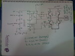
H-bridge.jpg
1) what is the use of C3 n how i'll calculate the value?
2) Exactly which back EMF protection Diode should i use as D' ?
3) Do i need to use an opto-isolator for high side nMosfets?

The intended frequency is 150KHz and the Mosfet's are N-type.
 

c3 is for dv/dt spike protection.

---------- Post added at 00:23 ---------- Previous post was at 00:04 ----------

the diode rating value will be dependent on the maximum current stored in the inductor and maximum transient from the inductance...


text from wikipedia ...Flyback diode - Wikipedia, the free encyclopedia
seek a diode which has very large peak forward current capacity (to handle voltage transients without burning out the diode), low forward voltage drop, and a reverse breakdown voltage suited to the inductor's power supply

**broken link removed**

---------- Post added at 00:28 ---------- Previous post was at 00:23 ----------

I dont think you need any isolation for mosfet....

Cant figure out any need here....

Can increase delay in your circuitry....
 

C3 is for filtering spikes and ripples, etc.
Circuit looks okay. Diode depends on the amount of current. What is the power of the induction heater? That may give a rough idea.

I don't see any error in the circuit.

Isolation isn't mandatory and I don't think you need it here.

For C3, use a ~100uF electrolytic capacitor (value not too critical) in parallel with a 0.1uF ceramic or tantalum capacitor.

Hope this helps.
Tahmid.
 

Hello Himz,
The cap c3 is used as low pass filter to eliminate the high frequency pulses and its value should be about 68uF(electrolytic) 50v,the cap c1/c2 you are using are bootstrap cap that also needs to be replaced with only one cap of value 68uF/50v.
The diodes may be used 1N4007 instead of 5818.I hope it will help you,Regards
 

mrarslanahmed said:
why to use capacitor in parallel with 100u
Since capacitors differ in their high-frequency characteristics (and capacitors with good high-frequency properties are often types with small capacity, while large capacitors usually have worse high-frequency response), decoupling often involves the use of a combination of capacitors. For example in logic circuits, a common arrangement is ~100 nF ceramic per logic IC (multiple ones for complex IC's), combined with electrolytic or tantalum capacitor(s) up to a few hundred μF per board / board section.
Decoupling capacitor - Wikipedia, the free encyclopedia


Exactly. It's for decoupling.

Hello Himz,
The cap c3 is used as low pass filter to eliminate the high frequency pulses and its value should be about 68uF(electrolytic) 50v,the cap c1/c2 you are using are bootstrap cap that also needs to be replaced with only one cap of value 68uF/50v.
The diodes may be used 1N4007 instead of 5818.I hope it will help you,Regards

It's better to add a decoupling capacitor across the bulk capacitor. The value of the bulk capacitor isn't too critical. 68u is okay, 100u is also okay.
Since he's working at 150kHz, he can use lower value bootstrap capacitors depending on the minimum duty cycle. 4.7uF, though, seems fine.

Hope this helps.
Tahmid.
 

the intended power is to reach 2KW.

---------- Post added at 21:14 ---------- Previous post was at 21:11 ----------

C3 is for filtering spikes and ripples, etc.
Circuit looks okay. Diode depends on the amount of current. What is the power of the induction heater?

The intended power is to reach 2KW.

---------- Post added at 21:15 ---------- Previous post was at 21:14 ----------

Hello Himz,
The cap c3 is used as low pass filter to eliminate the high frequency pulses and its value should be about 68uF(electrolytic) 50v,the cap c1/c2 you are using are bootstrap cap that also needs to be replaced with only one cap of value 68uF/50v.
The diodes may be used 1N4007 instead of 5818.I hope it will help you,Regards

Surely i'll use 1n4007. thanx for the advice.

---------- Post added at 21:21 ---------- Previous post was at 21:15 ----------

in the data sheet of IR211o there is also another cap between the Vdd and Vss of the Chip. Is it mandatory here in my circuit???

Another question:
The load will be a simple LC resonant circuit. And the inverter will be driven at the resonance frequency. So the LC circuit will react like a short-circuit with zero impedance. So what will be a better choice for impedance matching and to transfer 2KW to the load???

Power inductor at the both inputs to the load // simply a ferrite core transformer ?
 

You can use 1N4007 in place of D1. But not in place of D2 and D3. For D2 and D3 use ultrafast diode or schottky like 1N5818.
 

oh i forgot is 1N4007 is fast enough to charge the bootcap at 150KHz switching speed?? if not then, can any one give me a better suggestion for a fast high power diode?

---------- Post added at 23:17 ---------- Previous post was at 23:16 ----------

You can use 1N4007 in place of D1. But not in place of D2 and D3. For D2 and D3 use ultrafast diode or schottky like 1N5818.

ohh thanx..after just posting my reply i found your post!!
 

i find some error for u design...in decoupling capacitor connection ...but just very small error....for the voltage waveform a bit reflected ..just give u observed the waveform. i dontknow is software problem or i understanding wrong..maybe i should try in real life practical.......i use ur design to do in proteus...and follow ur explain to do H-bridge mosfet configuration

while i tested ur circuit...first i try to put a motor ..to test it ..this circuit worked or not...after success ..then i try to in spwm....


**broken link removed**

Uploaded with ImageShack.us


after i try to change connection in IR2110 ..btw in proteus dont have IR2110 ..so i use IR2112 instead of IR2112 should be not problem.....AFTer i found the error in decoupling capacitor connection....maybe also depend my luck i change the way to connect it....i solve the voltage reflected

**broken link removed**

Uploaded with ImageShack.us
 
Last edited:

Status
Not open for further replies.

Similar threads

Part and Inventory Search

Welcome to EDABoard.com

Sponsor

Back
Top