himz
Newbie level 3

Hi,
I was designing a High Power High frequency Induction Heater inverter. I choose H-bridge configuration for the inverter
and IR2110 gate drivers to drive the bridge. As the IR2110 is a half-bridge driver i'll use two of them to drive the both sides.
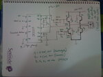
I've done a rough circuit(just drawing). As i dont know much about power electronics i wonder if there is any mistake.
i am looking for advice, recommendation, and any kind of error that should be fixed in my circuit.
Also i've some questions:

1) what is the use of C3 n how i'll calculate the value?
2) Exactly which back EMF protection Diode should i use as D' ?
3) Do i need to use an opto-isolator for high side nMosfets?
The intended frequency is 150KHz and the Mosfet's are N-type.
I was designing a High Power High frequency Induction Heater inverter. I choose H-bridge configuration for the inverter
and IR2110 gate drivers to drive the bridge. As the IR2110 is a half-bridge driver i'll use two of them to drive the both sides.
I've done a rough circuit(just drawing). As i dont know much about power electronics i wonder if there is any mistake.
i am looking for advice, recommendation, and any kind of error that should be fixed in my circuit.
Also i've some questions:

1) what is the use of C3 n how i'll calculate the value?
2) Exactly which back EMF protection Diode should i use as D' ?
3) Do i need to use an opto-isolator for high side nMosfets?
The intended frequency is 150KHz and the Mosfet's are N-type.


