Continue to Site

Welcome to EDAboard.com

Welcome to our site! EDAboard.com is an international Electronics Discussion Forum focused on EDA software, circuits, schematics, books, theory, papers, asic, pld, 8051, DSP, Network, RF, Analog Design, PCB, Service Manuals... and a whole lot more! To participate you need to register. Registration is free. Click here to register now.

Inrush current limiter NTC failures, what possible causes?

Status
Not open for further replies.

userx2

Full Member level 3
Joined
Sep 19, 2008
Messages
168
Helped
2
Reputation
4
Reaction score
3
Trophy points
1,298
Activity points
3,022
Hello,

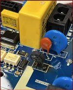
I have a design for US 120V operation with an NTC on the Live/Active line.
After being operational in the field for some 12 - 18 months, we are now getting many returns where this component has failed open circuit.


I was wondering what the cause of such a component going open circuit could be?
Are they sensitive to something?

There is no visible damage (has not blown up).

The component is EPCOS TDK B57235S0609M.
The loads on that line are a fridge compressor and a pressure pump. Both are triac controlled.

Since it takes such a long time to go faulty, I am not sure if there is something slowly wearing it out so to speak or a once in 18 months occurrence that causes the issue.

I am out of ideas at this stage and according to the calculations and the measurements we have done, the circuit is operating under the limits of NTC component.


All ideas and input will be greatly appreciated.
 

You say the circuit is operating under the limits of NTC component, well what are those operating conditions? does it include supply turn on/ supply turn off/ load transients /ambient temp?
 

Hi,

where is the electronics located? When thinking of a fridge compressor condensated water comes into my mind. And the datesaheet of the NTC makes the following statement.

In case of exposure of the NTC inrush current limiters to water, electrolytes or other aggressive media, these media can penetrate the coating and reach the surface of the ceramic. Low-ohmic or high-ohmic behavior may occur due to the formation of an electrolyte with metals (silver/lead/tin from metallization or solder). Low-ohmic behavior is caused by electrochemical migration, high-ohmic behavior by dissolving of the electrode. In either case, the functionality of the NTC inrush current limiters can not be assured.

But I assume the electronisc is not placed in the vicinity of the compressor and well housed. Might the movement, caused by the pump and compressore, "propagate" to the NTC causing an open-fault by the moevement?

Could you share a picture of the electronics and its location in (outside) the fridge?

BR
 

Hi,

Could you please upload a photo of the PCB with the ICL? (100kBytes should be sufficient)
TDK provides a lot of additional information on the product internet site. Did you read them? (At least: datasheet, application note, selection guide..)

You give us no information about the used load regarding size, current, control, timing ... and so on, thus we are not able to validate whether you selected the right ICL for your application.

Klaus
 

I appreciate all your input. Thank you.
I have to be careful what I share as it is not allowed. I will see what else I can say.

The NTC is on a circuit board, inside a housing. There is another identical NTC on the PCB and that one so far has not failed at all.

The maximum ambient temperature at the PCB is 55 degC.

I have read most if not all the EPCOS TDK information.
I am however still not clear on how to use Ctest parameter for selecting these parts..
There is a small compressor with 14A locked armature or inrush current and 171W operating power.
And a pump specified is 1A max pressure depending.

When I said the circuit is operating under the limits of the NTC, it is as far as steady state current goes.

The 2 turn on and off individuslly, each with triac control.
There is a chance tgat they might turn on at the exact same time.
But I am not sure if that can cause a problem for the NTC.

Is failing open circuit any indication on what might be happening? I mean compared to failing visibly with smoke?
 
Last edited:

Cyclic endurance of NTC is tested for 1000 cycles. If your application involves more than a few cycles/day, it's outside guaranteed performance.

Extra stress can be expected if the high inrush current device is switched on before the NTC has cooled down.
 

Hi,

Ctest:
The standard application for these ICTs are power supplies.
Power supplies have a rectifier and a big capacitor to be charged.
Usually the capacitor will draw high inrush current .. without the ICT.

But looking at the chart for the current vs time you see this is a timing range of a couple of milliseconds.
But starting a motor may take several 100 milliseconds.

Since the ICT acts like a series resistor ... a lot of power (--> heat) is dissipated during current limiting.
Or better say a lot of energy. "Energy" is a better measure here, because it also includes "time".

********
Other important things:
* a closed case and parts around the ICT will reduce air flow. This leads to overheating. This is why we want to see the PCB.
* bending wires: often cause the coating to get invisible small cracks. But humidity will find it's way inside. This is one known reasons for long time failure.

This again is why we wanted to see a photo. A photo tells more than many words. And in opposite to text it does not only show what you think "is important" .. it shows much more.

Klaus
 
Using a common NTC for two individually timed motors doesn't seem right. I doubt that an inrush current limiter is necessary for a motor with 14 A peak current.
--- Updated ---

https://groups.io/g/LTspice/ has a SPICE model for the S235/6 NTC, it can be used to simulate the current characteristic with different loads.
 
Regarding Ctest:
I figured that a load could be represented as a capacitor but I am not able to convert the loads I have to an equivalent capacitor, based on the values I have.
What stumped me is tfat the test circuit in the documentation discharges Ctest into the NTC. In other words, a finite charge or energy is dumped into the NTC.
Is that the same as said capacitor being charged through the NTC?
I suppose it is but why then show it like they do, back to front?

I need toto investigate if multiple cycles/restarts can happen. The firmware is complex.

@ Klaus:
I fully understand and would love to elaborate. I will check with my boss tomorrow.
I will investigate for cracks around the lead entries. The PCB footprint pitch matches the part and tge legs shoukd be straight and not stressed. But I will check samples.
The housing is fan cooled.
--- Updated ---

Using a common NTC for two individually timed motors doesn't seem right. I doubt that an inrush current limiter is necessary for a motor with 14 A peak current

They apparently had issues with occasionally exploding triacs before. The NTC stopped that problem completely.

Also, the system is fused at 15A and there are otyer loads in the system as well.
I do not know the full history of this design.

BTW, there is a 240V version of this circuit and product and there have never been any failures. But then again, it is the same circuit but different parts.
 
Last edited:

What stumped me is tfat the test circuit in the documentation discharges Ctest into the NTC. In other words, a finite charge or energy is dumped into the NTC.
Is that the same as said capacitor being charged through the NTC?
I suppose it is but why then show it like they do, back to front?
Yes, the behaviour is equivalent. A popular setup to do the test with a current/power limited lab supply.

As previously mentioned, it might turn out that the cycle count of your application isn't suitable for NTC current limiters.
 

Do you mean that the unit might be exceeding the no. of cycles?
I will look into that as well but was not aware that there is a limit on an NTC.

The 240V version mentioned has identical operation but no failures in years.
 

240V version is using same S235/6 PTC?
I only just managed to verify that now. Yes, it is the same part used for 240V.
--- Updated ---

Question:
If the second load kicks in while the first one is already operational, would the second inrush current overload the NTC?
It is not clear to me whether that second inrush then falls under the steady state current or not.
 
Last edited:

If the second load is switched on with hot NTC, it produces maximal inrush current. Just omitting the partly nonfunctional NTC won't increase the inrush current much.
 

My previous description was incorrect. I have had a look at pictures of some more of the returned boards and I have to say that the NTC is visibly blown up actually on most of them.

Regarding the second load starting after the first load has caused the NTC value to drop, that is very possible.
But I It would be similar to one load restarting with hot NTC also.

What I do not understand in that case if that could overload the NTC or not. Since it is only a short surge, I can't see that condition falling under the max steady state current. Or?

When exactly does the parameter Pmax (1.8W) apply? Under normal inrush with this motor at 14A, I simulate some 400W power across the NTC for a short period.
Is it safe to presume that this would be completely normal for these components?

The datasheet does not give a maximum energy burst that this can handle or do they by means of that Ctest?
how would I even calculate that for this application? I do not have the I vs t curve of the motor inrush current.
Plus, I think that curve would get influenced by the NTC being present.
I would guess, that the lower inrush current will be prolonged prolonged with the NTC fitted.
 

Here is a picture of the problem. The PCB has some discoloring on the coating from heat as well.
Something must be happening that is not taken into account.
 

Attachments

  • PCB NTC issue.JPG
    PCB NTC issue.JPG
    58.7 KB · Views: 176

120Vac = 2 x the current than for the 230Vac, = 4 x the heat in the ntc, both for the starts and the run time

simple really
 

120Vac = 2 x the current than for the 230Vac, = 4 x the heat in the ntc, both for the starts and the run time
Presume the supply voltage variants are also using different motors and hence have different inrush current magnitude. This is probably the reason why you don't experience failure of the 230V design, may be just by chance.
Regarding the second load starting after the first load has caused the NTC value to drop, that is very possible.
But I It would be similar to one load restarting with hot NTC also.

What I do not understand in that case if that could overload the NTC or not. Since it is only a short surge, I can't see that condition falling under the max steady state current. Or?
Starting with hot NTC (stop period < NTC cooling time) should not happen (or at least only very rarely) with NTC inrush limiter, otherwise early failure is likely to happen. As previously mentioned, the intended current limiting purpose isn't achieved in this mode of operation, you can better run it without NTC.

Unlike rectifier+capacitor load, a motor already involves a winding resistance limiting the current. I guess that relating the winding resistance to NTC cold resistance of 6 ohms shows a rather small effect, so it can be safely omitted.

I've seen cracked NTC like in your photo occasionally, e.g. in small single phase input VFD inverters. Reason was most likely too many power cycles and particularly too many turn-on with hot NTC.
 
Last edited:

Agreed.
I have since obtained 120V compressor and pump and measured the current.
Shock horror, the compressor has indeed a 14A inrush current as specified in the datasheet but it is RMS not peak.
I measured up to 26A peaks there on 1 half cycle.

But the killer is that this high current persists for 6 (!) full mains cycles. I calculated the energy of that to be ~158J.
The power over the NTC is 500W at the start and 200W of the end of the inrush current.

The situation actually improves the higher ambient temperature of 55dC since the initial resistance is lower, there is less power consumed by the NTC.

Either way, this circuit needs revising. I am not sure how as there is no space on that PCB for much bigger components. I am also wondering if an NTC is even the right solution at all in this case.
--- Updated ---

I now wonder what could be done instead. I doubt any NTC (of a size that can fit there) could fix this problem.
 
Last edited:

In the first place, I would check if the circuit can operate without inrush current limiter. It's quite normal that compressors (e.g. refrigerator, HVAC) run directly from mains power.

I have used a Danfoss compressor in an analytical instrument, it's controlled by a power relay. If I remember right, the compressor has an internal starting circuit, an external series resistor might conflict with it.
 

Status
Not open for further replies.

Similar threads

Part and Inventory Search

Welcome to EDABoard.com

Sponsor

Back
Top