DeboraHarry
Full Member level 5

I've tried to simulate using HFSS a thin half-wave dipole which is immersed in a perfect dielectric with Er=81. (This is the same dielectric constant as water, but I used a perfect dielectric for the simulations to get a feel for the results, and to later see how much the conductivity of real water effected the antenna's properties).
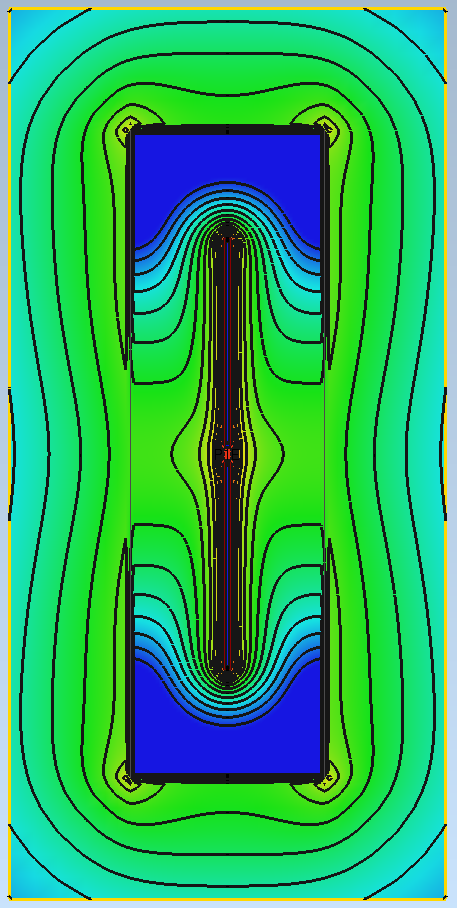
I calculated the free space length for the dipole, then shorted it by a factor of sqrt(81)=9. This was then put in a cylinder which had Er=81. The cylinder had a radius of lambda/4 (in the dielectric) around the dipole. The length of the cylinder was lambda. So the dipole was surrounded by dielectric for a quarter wave, where the quarter wave was that in the dielectric - not in air.
An airbox, which surrounded the dielectic by lambda/4 (in air), was put around the dielectric. This was of course much larger than the dielectric, as the wavelength is 9x bigger.
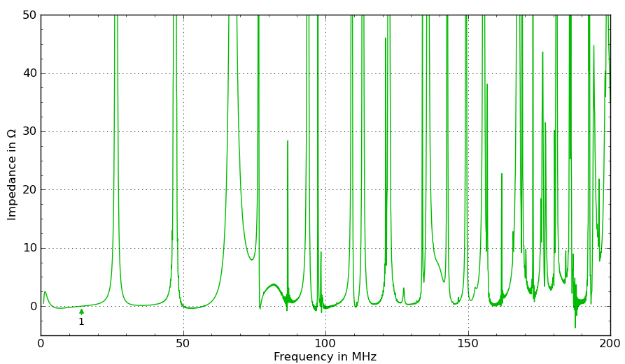
The reasonate frequency calculated in HFSS was close to what I expected. However, at resonance, the real part of the input impedance was only 0.02 Ohms, which is smaller than the free space input impedance by a factor of 3600. (73/0.02=3600). This seems really odd to me.
I changed the point at which HFSS stops refining the mesh so that |S| was 0.01, rather than the default 0.02. I also changed it so there was at least 3 converged passes. This was basically so I could see the result was stable.
What I also did was to ensure the size of the mesh was not more than lambda/6 on both the surfaces of the dielectric and the airbox. The mesh was forced to be much finer (by a factor of 9) on the surface of the dielectric.
Any thoughts what the input Z should be, and if is not 0.02 Ohms, what might be wrong with my HFSS simulation
I calculated the free space length for the dipole, then shorted it by a factor of sqrt(81)=9. This was then put in a cylinder which had Er=81. The cylinder had a radius of lambda/4 (in the dielectric) around the dipole. The length of the cylinder was lambda. So the dipole was surrounded by dielectric for a quarter wave, where the quarter wave was that in the dielectric - not in air.
An airbox, which surrounded the dielectic by lambda/4 (in air), was put around the dielectric. This was of course much larger than the dielectric, as the wavelength is 9x bigger.
The reasonate frequency calculated in HFSS was close to what I expected. However, at resonance, the real part of the input impedance was only 0.02 Ohms, which is smaller than the free space input impedance by a factor of 3600. (73/0.02=3600). This seems really odd to me.
I changed the point at which HFSS stops refining the mesh so that |S| was 0.01, rather than the default 0.02. I also changed it so there was at least 3 converged passes. This was basically so I could see the result was stable.
What I also did was to ensure the size of the mesh was not more than lambda/6 on both the surfaces of the dielectric and the airbox. The mesh was forced to be much finer (by a factor of 9) on the surface of the dielectric.
Any thoughts what the input Z should be, and if is not 0.02 Ohms, what might be wrong with my HFSS simulation