Continue to Site

Welcome to EDAboard.com

Welcome to our site! EDAboard.com is an international Electronics Discussion Forum focused on EDA software, circuits, schematics, books, theory, papers, asic, pld, 8051, DSP, Network, RF, Analog Design, PCB, Service Manuals... and a whole lot more! To participate you need to register. Registration is free. Click here to register now.

Input impedance and output impedance clarification...

Status
Not open for further replies.

subbuindia

Member level 5
Joined
Dec 13, 2011
Messages
87
Helped
11
Reputation
22
Reaction score
10
Trophy points
1,288
Location
Vellalacheruvu(AP), India
Activity points
1,908
Hi Friends...

I've some doubt regarding the requirements of input impedance and output impedance of any device/circuit. We all know that one of the advantage of MOSFET over FET is:

1. "The input impedance of MOSFET is high compared to FET and output impedance of MOSFET is less compared to FET".

I'm writing other statement regarding the advantage of current mirror circuit :

2. "The input impedance of current mirror is less and the output impedance of current mirror is high (of course, I've taken practical conditions)".

From the above two statements, I'm confusing the "what are the requirements of input and output impedance of any device/circuit". Simply, my question is "The requirement of input impedance of any device is high or low. Which one is correct.? If both are correct in different applications, how can designers decide the characteristics of any device/circuit in terms of input impedance and output impedance". Thank you in advance..
 

When you convey information, it's better to have low output impedance feeding high input impedance. The aim is to avoid 'loading' the output.

When conveying power, it's better to match impedance. Example, an audio amplifier driving a speaker. You certainly don't want the amplifier to have high output impedance.

- - - Updated - - -

It's certainly okay for the amplifier to be capable of low output impedance. But assuming our aim is to fully utilize the entire range of supply voltage, then we make its average impedance match load impedance.
 
.......................
When conveying power, it's better to match impedance. Example, an audio amplifier driving a speaker. You certainly don't want the amplifier to have high output impedance.
....................
That may be true for RF transmitters and some other RF circuits, and old tube (valve) amps, but not for modern solid-state audio amps.
They normally have a much lower output impedance than the load (speaker) impedance.
Their design is for maximum efficiency not maximum output power where the power is limited by the power supply voltage and current capability, not the amplifier output resistance.
 
Hi,

A philosophic question: Is an audio amp made to convey power or information or both?

Klaus
 

That may be true for RF transmitters and some other RF circuits, and old tube (valve) amps, but not for modern solid-state audio amps.
They normally have a much lower output impedance than the load (speaker) impedance.
Their design is for maximum efficiency not maximum output power where the power is limited by the power supply voltage and current capability, not the amplifier output resistance.

Your answer is more complete than mine. Perhaps my reply addressed something other than the main principle of impedance matching. I was thinking of voltage swings at the speaker. For optimum performance we try to utilize the maximum amplitude available, without clipping. This results in equal voltage swings on either side of Vcc/2. When we do this we make the effective average output impedance identical to the speaker impedance.
 

"Optimum performance" of an audio amplifier is not maximum output amplitude and awful sounds.

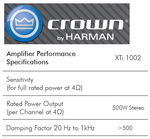
A modern audio amplifier has a specification called "Damping Factor". A good damping factor damps resonances of a speaker so it does not ring like an old sound system did or like a bongo drum. Many good audio amplifiers have a damping factor of more than 500 so the output impedance is less than 8 ohms/500= 0.016 ohms then the speaker does not resonate but exactly follows the signal perfectly. Maximum amplitude is easy to have by using a suitable supply voltage.
 

Attachments

  • amplifier damping factor.png
    amplifier damping factor.png
    34.4 KB · Views: 198

Your answer is more complete than mine. Perhaps my reply addressed something other than the main principle of impedance matching. I was thinking of voltage swings at the speaker. For optimum performance we try to utilize the maximum amplitude available, without clipping. This results in equal voltage swings on either side of Vcc/2. When we do this we make the effective average output impedance identical to the speaker impedance.
I don't see that having the output swing symmetrical around Vcc/2 has anything to do with the "average" output impedance. How do you calculate that?

Typically a single supply audio amps biases the output to a DC level of Vcc/2 and then capacitively couples the amp to the speaker to block the DC bias.

As a matter of fact to achieve the maximum peak output voltage symmetrical around Vcc/2 you actually need an output impedance of zero.
Anything greater than zero will reduce the maximum voltage to the speaker.

I agree to have maximum AC power, output impedance must go near zero for part of the waveform. And there is also the part of the waveform where impedance becomes very high. That is how to get greatest extremes of voltage swing.

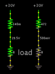
Suppose we want load voltage to swing between the supply rails, and approach within 1/2V of each rail. (Load 8 ohm, supply 30VDC.) Amplifier impedance needs to be .14 ohm at one extreme in the cycle. Then at the opposite extreme the amplifier needs to be 472 ohms, which is not a very low value. Yet a high value is needed to create large amplitude across the load.

(The upper resistor is a simple imitation of a class A amplifier.)

1539066900_1474436236.png


Should we expect that effective impedance is the average of 472 and 0.14? No, that gives 236 ohms and that can't be right.
The geometric mean is 22 ohms, but that doesn't seem right either.
We can calculate that since average load voltage is Vcc/2, then the amplifier's effective impedance is the same as the load impedance, 8 ohms.
 

.................
We can calculate that since average load voltage is Vcc/2, then the amplifier's effective impedance is the same as the load impedance, 8 ohms.
Well, that's an interesting calculation for that particular set of circumstances but you're the only one I've ever seen make that calculation for an audio amp. If the amplifier were a bridge design where the average output was Vcc, then your calculation of the "effective output impedance" would be different for the maximum output signal.

And that calculation is really not related to matching the output impedance to the load impedance to achieve maximum power, which is a deliberate act, not an incidental function of the amps operation.
The normal definition of an amps output impedance is calculated from the IR drop for the output between the open circuit voltage and the load voltage which, as AG noted, is much less than an ohm for modern solid-state audio amps.
 
Brad, we do not feed a DC voltage swing to a speaker, instead we feed it AC then the impedance of the amplifier must be low all the time for the most output swing, positive-going and negative-going. Since the amplifier output impedance is very low then it damps resonances of the speaker so it does not sound like a bongo drum.

The impedance of a speaker at its resonant frequency is high so if the amplifier impedance matches its nominal impedance then there will be a 6dB peak in the frequency response at resonance in addition to the ringing caused by poor damping.
 
And that calculation is really not related to matching the output impedance to the load impedance to achieve maximum power, which is a deliberate act, not an incidental function of the amps operation.

Yes, valid point. In the back of my mind was the transformer needed between a speaker and amplifier (particularly years ago with tube amps as post #3 refers to). That is a proper application of impedance matching. Transformer design is deliberate.

Solid state audio amps have some advantages over tube amps. Such as low output impedance. Solid state type need no transformer. Just the same, we might wonder which principles of impedance matching still apply? Such as the statement which says that for maximum power transfer, impedances should match?

- - - Updated - - -

Brad, we do not feed a DC voltage swing to a speaker, instead we feed it AC

Yes, and a class B amplifier should make a better example than my post #8, because it delivers true AC. But in the simple form the speaker sees only positive supply or negative supply at a given moment. And it sees that supply voltage through varying resistance of the transistor. Only one transistor is turned on at any moment. Because we have more or less symmetrical behavior, I simplified it to the diagram in post #8.
 

Yes, valid point. In the back of my mind was the transformer needed between a speaker and amplifier (particularly years ago with tube amps as post #3 refers to). That is a proper application of impedance matching. Transformer design is deliberate.

Solid state audio amps have some advantages over tube amps. Such as low output impedance. Solid state type need no transformer. Just the same, we might wonder which principles of impedance matching still apply? Such as the statement which says that for maximum power transfer, impedances should match?
.................
Tube amps had to have an output transformer since tubes (valves) had a relatively high impedance and their maximum power was also limited so you wanted to match the load to the tube impedance for maximum power transfer, with no particular concern about overall efficiency.
(Although I have seen tube designs that used many large tubes in parallel to lower the output impedance and eliminate the need for a transformer).
In those days, 20W to 40W per channel was considered a fairly high power amplifier

But don't get hung up on the maximum power transfer theorem.
It generally doesn't apply to low output impedance devices, such as a solid-state amp or a power supply.
Power transistors have such a low impedance (MOSFETS can have a few milliohms or less) that it's not desirable or practical to match the load to this impedance, since the power supply is now the limiting factor. The maximum power is determined by the power supply rating from the power transformer and rectifier limits, not the amp source impedance.
This also means the overall efficiency is higher than a matched load would give.
 
An audio amplifier is not simply one or two transistors that are used to drive LEDs. Instead it uses many transistors so that its open-loop gain is in the thousands and plenty of negative feedback causes its output impedance and distortion to be very low. Then the output transistors are not simple variable resistors in series with the speaker, the output is a voltage source with almost no series resistance. Then the speaker's cone accurately follows the signal.
 
I'm finding this discussion is of benefit, to give me further clarification. However I have a hunch the original question was supposed to be about situations that the OP had in mind? I apologize if I took off on a side-track topic. Anyway this is the thread where the question can get further clarification.
 

In the first post the first statement, "The input impedance of MOSFET is high compared to FET" is wrong. BOTH have a high input impedance if the input is at the gate pin.
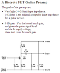
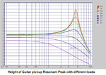
Here is the schematic of the preamp for an electric guitar magnetic pickup that uses a Jfet. The input impedance is high at 3M because we want the pickup coil and the capacitance of its cable to resonate and produce the "twang" sound.
 

Attachments

  • guitar preamp.PNG
    guitar preamp.PNG
    15.4 KB · Views: 159
  • Guitar pickup peak.PNG
    Guitar pickup peak.PNG
    73.1 KB · Views: 163

If it can be done, more power will be transferred to the load if the source impedance is lowered instead of matching the load to the source.

Ratch
 

Status
Not open for further replies.

Part and Inventory Search

Welcome to EDABoard.com

Sponsor

Back
Top