Continue to Site

Welcome to EDAboard.com

Welcome to our site! EDAboard.com is an international Electronics Discussion Forum focused on EDA software, circuits, schematics, books, theory, papers, asic, pld, 8051, DSP, Network, RF, Analog Design, PCB, Service Manuals... and a whole lot more! To participate you need to register. Registration is free. Click here to register now.

Increase meter sensitivity in frequency to voltage converter

Status
Not open for further replies.
Try linking the emitters together and grounding them through a single resistor (try 1K). The transistors MUST be thermally bonded so any change in temperature has the same effect on both.

Brian.
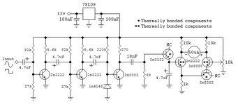
I did not thermally bonded them I just blew air onto both of them. Ok I will do so. Isn't a balance pot needed at the emitters? Or is it taken care of from the other pot in the input of one of the two transistors?
 

A balancing pot between the two emitters, with a fixed resistor from it's wiper to ground will adjust the relative effect each transistor has on the meter reading. One way will make it more sensitive to the frequency output, the other way more sensitive to the zero adjustment. You would have to experiment to find the optimum position but the transistors would still need thermal bonding so that their characteristics track each other.

Brian.
 

    neazoi

    Points: 2
    Helpful Answer Positive Rating
Try linking the emitters together and grounding them through a single resistor (try 1K). The transistors MUST be thermally bonded so any change in temperature has the same effect on both.

Brian.
Ok, I think I am in the right direction.
I experimented by replacing the detector diode with the B-E junction of the same type of plastic transistors I use for the bridge. This was done so as to have devices with similar thermal characteristics and to physically be able to bond them together. I also used an extra such "diode" at the right end.

The right end of the bridge increases the frequency when heated, whereas the left end and the detector diode, decreases it.
Because I am using the same BJTs also for the diodes, the system comes into balance. Note how I paired the thermally coupled BJTs. It doesn't really matter as long as you pair one of the right ones to one of the left ones.

Now when I touch my finger at the same time onto these 4 transistors I get no shift.
Before, with the discrete diodes I did so.

However when I still blow on the circuit the frequency still shifts. There must be another source which I need to find out.
 

Attachments

  • detector.png
    detector.png
    9.9 KB · Views: 83

If you don't mind using IC's you can make a basic frequency counter from several 4017 decade counters, and a bunch of led's. Attach ten led's to each 4017. This creates columns indicating ones, tens, hundreds, thousands. (Maybe you don't require +1-1 precision? Then omit the ones column of led's.)

Add logic which lights the columns of led's so they give a readout of frequency.
Then reset the array once per second.

This method is as accurate as the device you use for a 1 second timer. It doesn't generate errors due to components heating.
 
Last edited:

If you don't mind using IC's you can make a basic frequency counter from several 4017 decade counters, and a bunch of led's. Attach ten led's to each 4017. This creates columns indicating ones, tens, hundreds, thousands. (Maybe you don't require +1-1 precision? Then omit the ones column of led's.)

Add logic which lights the columns of led's so they give a readout of frequency.
Then reset the array once per second.

This method is as accurate as the device you use for a 1 second timer. It doesn't generate errors due to components heating.
It might be, however, I doubt it will work well on noisy signal conditions. If you have a clean channel ok, but if there are even sudden noises. I believe that the charging capacitor method that the discrete meter uses, is more forgiving to sudden noises, spikes etc. It is just a speculation, I do not want to argue on it.
 

Hi,

the "charging capacitor" acts like a filter.
You are free to use a filter (like simple RC low pass) with ICs, too.

Klaus
 

After a closer examination, I was able to find the last source of thermal drift. It was this 270R at the collector of the final transistor before the 10nF capacitor.
This get hot and even blowing onto it causes the frequency reading to drift down.
I replaced it with 2W resistor, and things improved, but it was still a bit hot. I replaced it with two 560 ohms in parallel and things improved even more, but there is still heat in them and some drift (less now).
Instead of using that large wattage resistor, I would like to compensate for the thermal drift on it.
Maybe another B-E junction of a 2n2222 placed in series with this resistor and thermally bonded to another component?
I could also use a larger value resistor to decrease heat, but I do not know what effect this will have in the circuit performance (immunity to input signal level), so I prefer compensation.
Any other idea?
 

I suspect its the heat radiated from the resistor rather than its value changing that causes the problem but in theory there is no reason a much higher value can't be used. Try going 10x in value to 2.7K and compensate by dropping the 18nF capacitor to 1.8nF. It is the chain of 270 Ohms, 18nF, 68 Ohms that gives you the frequency filtering so you should be able to offset a resistance change with an equal but opposite capacitance change.

It still wont fix the problem of such small difference in filter output over a small frequency range though.

Brian.
 

    neazoi

    Points: 2
    Helpful Answer Positive Rating
Status
Not open for further replies.

Part and Inventory Search

Welcome to EDABoard.com

Sponsor

Back
Top