Continue to Site

Welcome to EDAboard.com

Welcome to our site! EDAboard.com is an international Electronics Discussion Forum focused on EDA software, circuits, schematics, books, theory, papers, asic, pld, 8051, DSP, Network, RF, Analog Design, PCB, Service Manuals... and a whole lot more! To participate you need to register. Registration is free. Click here to register now.

Increase IR range

Status
Not open for further replies.

ElectricalStudent

Newbie level 4
Joined
Mar 14, 2022
Messages
7
Helped
0
Reputation
0
Reaction score
0
Trophy points
1
Activity points
55
Hello everyone,
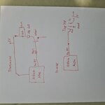
I am trying to find way how to increase the range of IR. Im using transmitter Ir 333 and reciver TSOP348.
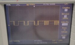
Also,I wrote a program in the microcontroller (Arduino) in order to make sure thats the trasmitter will transmit at 38Khz frequency at modulation frequency 100Hz.
Up to 2.5m the connection is great but after 3m I dont have connection.
How can i increase the distance from 2.5m to 5m?
Thank you.
 

100 Hz is probably too slow for optimal response. Review receiver datasheet about maximal burst length. What's the transmitter current?
 

Hi,

* Tx and Rx face to face
* lenses, reflector
* increased current
* different type --> IRDa
* multiple LEDs
* repeater
* ...

Klaus
 

I tried to connect 2 leds in parallel but it didnt really helpd me.
Its really strange:
From 0 meter to 2.5 meters it really works great. But above it ,i have to block the transmitter with my hand and only in this way after i realease my hand it detects again the signal.
 

100 Hz is probably too slow for optimal response. Review receiver datasheet about maximal burst length. What's the transmitter current?
The 100hz is the requirment of this project..
I am attaching the picture fron the scope.
This is how it looks like at 2.5m .
 

Attachments

  • Screenshot_20220314-225953_Gallery.jpg
    Screenshot_20220314-225953_Gallery.jpg
    452.7 KB · Views: 116

Hi,

Quite expectable when there is a current limiting device.

For a detailed answer we need to see the circuit.

Klaus
This is my current circuit.
Im reading the received data from pin 9 in the Arduino Mega.
 

Attachments

  • 16472922899622583662253911696051.jpg
    16472922899622583662253911696051.jpg
    2 MB · Views: 129

Hi,

Did you design the circuit on your own?
Dud you verify voltage drop across the resistors with the scope?

Driver circuit:
* let's assume the supply voltage is 5.0V and stays constant (verify both with a scope)
* let's assume V_CE_on is 0.5V
* let's assume the LED_voltage is 1.4V (don't know what type you use)
Then the LED current should be limited by the resistors to (5.0V - 0.5V - 1.4V) / 5Ohms = 3.1V / 5Ohms= 0.62A
--> I guess there's something wrong with my assumptions...

Paralleling diodes will not give much benefit. Since the voltage drop across parallelde diode does not change that much ..
This means the total current does not change that much, either.
Thus the ammount of light does not change that much.

Klaus
 
Last edited:

Yes I designed it alone.
How do you think i can change the circuit in order to increase the range?
Thank you.
Hi,

Did you design the circuit on your own?
Dud you verify voltage drop across the resistors with the scope?

Driver circuit:
* let's assume the supply voltage is 5.0V and stays constant (verify both with a scope)
* let's assume V_CE_on is 0.5V
* let's assume the LED_voltage is 1.4V (don't know what type you use)
Then the LED current should be limited by the resistors to (5.0V - 0.5V - 1.4V) / 5Ohms = 3.1V / 5Ohms= 0.62A
--> I guess there's something wrong with my assumptions...

Paralleling diodes will not give much benefit. Since the voltage drop across parallelde diode does not change that much ..
This means the total current does not change that much, either.
Thus the ammount of light does not change that much.

Klau
 

The 100hz modulation i'm creating with the software. At short distances i see it at the scope.
Means the kHz pattern shown in post #5 is not sent by the IR diode but generated by the receiver? This supports my doubt that the receiver isn't suited to process bursts of 5 ms duration.
 

Hi,
How do you think i can change the circuit in order to increase the range?
You did not react on: lens, reflector, different IR system, face to face.... please give feedback what is possible, or not, and why..

The IR LED is specified with 100mA average.
Thus assuming a duty cycle of 50% you must not go beyond 200mA LED peak current (assuming high enough frequency)

I talked about supply to be 5.0V and to be stable (during IR operation). No feedback from your side.
I talked about verifying the voltage drop across the resistors. No feedback...
But this is urgent to find out which way to go.

Or do you want us to recommend lower value resistors ... with the result that the IR diode gets killed?

Klaus
 

A different IR system is a great option but I don't know how to design the circuit. The continuous current in my IR 333 is 100mA according to the datasheet but I tried to calculate the current using a multimeter and I saw that the current is only 60 mA (Can't understand how it's possible. If I calculate the current using the equation (5-1.2-0.2)/5 I see that the current have to be higher.
I can take a smaller resistor. But I think it will affect the distance that I can transfer the signal.
The option of another IR system is a possible option but as a requirement of my project, I have to use modulation frequency 100HZ and modulated system 38Khz. (This I get from my Arduino-I wrote software that is doing it.
 

According to TSOP348xx datasheet, a minimum gap time of 4x burst time is needed for burst lenght > 70/f0 (=1.8 ms). This is due to the built-in filter for 100 Hz modulated light received from inverter operated fluorescent lamps.

Your 100 Hz/50 % duty cycle modulation pattern will be definitely suppressed by the filter. You might check if reducing the duty cyle to 20 % can improve sensitivity.
 

More power is not likely to solve this. Please put 10nF+10pF decoupling capacitors across power rails at both transmitter and receiver to rule out power supply issues.

Then include traces across Rc in transmitter and receiver output at 2.5 meters.
 

Hi,

even 10uF for 100ms burst with 100mA isn´t oversized.

I saw that the current is only 60 mA (Can't understand how it's possible.
Guess why I recommended twice now to verify power supply and voltage drop across the resistor with a scope.

Klaus
 

Start with the diode, the absolute max ratings are being exceeded, you may
have damaged the diode -

1647340330992.png


Notice the pulse constraints on the diode Imax, you are way over that. In addition if 50% duty cycle
and you are driving 1A thru diode, with its min Vf, you are dissipating ~ 1A x 2.6V (typ) x 50% =
1.3W (which is conservative), and spec limit is 150 mW

1647340505621.png


I am guessing those diodes are toast now....Not to mention the NPN (I think its 2N4401) has its
own constraints ....I cant read the base R value in your schematic, but if you drive 1A thru collector
rule of thumb is to sat the transistor you force beta at 10, which means you drive 100 mA into
base, which Arduino cannot possibly do.

Then you should calculate the photometrics of the link, LED is 20 degree, so what is power
out at 4 Meters falling on receiver ?

Picture of prototype transmission and receive side .....?


Rewgards, Dana.
 
Last edited:

Fortunately diode current is effectively limited by base resistor of 1k and 2N4401 current gain. May be it's sligthly above specified maximum but probably not much.

To determine if the diode is overloaded, actual peak and average current (respectively series resistor voltage drop) should be observed with an oscilloscope.

Used IR333 is similar to TSAL6200 mentioned in TSOP348 test setup, a range of several 10 m should be achievable, but only with suitable modulation pattern, see above.
 

Status
Not open for further replies.

Part and Inventory Search

Welcome to EDABoard.com

Sponsor

Back
Top