yolco
Member level 2

Hi,
after having designed some custom PCBs, a main one with an ARM MCU and other peripheral boards.But there is one issue when peripheral boards are plugged into the main one.
Please, let me introduce the issue and the tests I have done, in order to someone can help me to understand and figure out what is the root cause of the failure.
Main board is sourced by a Li-Ion battery, and it also has an USB connector to power the electronics and charge the battery; voltage from USB is converted to 3V3 with a LDO (@600mA). This LDO also supplies to peripheral boards.
- MCU's maximum current consumption is 250mA.
- Peripheral board's maximum current consumption is <100mA.
LDO can deliver enough current to main and peripheral boards if it is needed.
- Communication between boards, I2C protocol.
- Communication between main board and PC, serial port.
The issue comes when peripheral board is plugged into main board directly.
If the peripheral board pins are completely inside the main board sockets, there is no communication between boards, I2C fails. But main board continues communicating with PC through serial port without any inconvenience, or being programmed through JTAG.
Test1:
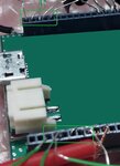
To enable communication between boards, peripheral board has to be semi-connected by its pins, at left side (please, see picture1 attached).

This left side has only power pins and interruption pins. Interruption pins are not used during the test. They are set, by the MCU, as pull-ups to avoid floating points, and disabled from the different sensors. So, these pins should not drain current.
Test2:
To check the behaviour of the peripheral boards, I have soldered wires to the pins of the peripheral boards, so I can connect them to other commercial boards, as arduino. They work fine.
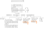
But the surprise appears when peripheral board is connected through wires to the main board, it works! (picture2 attached).

There is no issue with this configuration, even with all the interruption pins connected.
Question:
Which could be the root cause of this failure? How can I figure out what is happening here?
Assumptions:
At first time, I thought about power consumption issue, but even theoretical calculations were wrong, and sensors drain such amount of current, main board's serial port should not work neither.
Maybe, floating points due to interruption pins, but this should be fixed with IO's pull-up configurations. Moreover, it must be reproduced with the wire connection.
* I would provide more info if there is something not clear enough.
Hoping someone can help me.
KR!
after having designed some custom PCBs, a main one with an ARM MCU and other peripheral boards.But there is one issue when peripheral boards are plugged into the main one.
Please, let me introduce the issue and the tests I have done, in order to someone can help me to understand and figure out what is the root cause of the failure.
Main board is sourced by a Li-Ion battery, and it also has an USB connector to power the electronics and charge the battery; voltage from USB is converted to 3V3 with a LDO (@600mA). This LDO also supplies to peripheral boards.
- MCU's maximum current consumption is 250mA.
- Peripheral board's maximum current consumption is <100mA.
LDO can deliver enough current to main and peripheral boards if it is needed.
- Communication between boards, I2C protocol.
- Communication between main board and PC, serial port.
The issue comes when peripheral board is plugged into main board directly.
If the peripheral board pins are completely inside the main board sockets, there is no communication between boards, I2C fails. But main board continues communicating with PC through serial port without any inconvenience, or being programmed through JTAG.
Test1:
To enable communication between boards, peripheral board has to be semi-connected by its pins, at left side (please, see picture1 attached).

This left side has only power pins and interruption pins. Interruption pins are not used during the test. They are set, by the MCU, as pull-ups to avoid floating points, and disabled from the different sensors. So, these pins should not drain current.
Test2:
To check the behaviour of the peripheral boards, I have soldered wires to the pins of the peripheral boards, so I can connect them to other commercial boards, as arduino. They work fine.
But the surprise appears when peripheral board is connected through wires to the main board, it works! (picture2 attached).

There is no issue with this configuration, even with all the interruption pins connected.
Question:
Which could be the root cause of this failure? How can I figure out what is happening here?
Assumptions:
At first time, I thought about power consumption issue, but even theoretical calculations were wrong, and sensors drain such amount of current, main board's serial port should not work neither.
Maybe, floating points due to interruption pins, but this should be fixed with IO's pull-up configurations. Moreover, it must be reproduced with the wire connection.
* I would provide more info if there is something not clear enough.
Hoping someone can help me.
KR!


