Continue to Site
Follow along with the video below to see how to install our site as a web app on your home screen.
Note: This feature may not be available in some browsers.
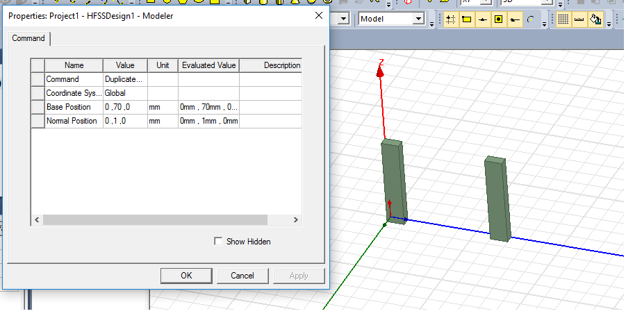
") can you tell me why the position changed from 70 to 1 on what basis you have made that??
can you tell me why the position changed from 70 to 1 on what basis you have made that??

Please explain a bit about your problem
What is beam and what you want to measure

