vbhupendra
Full Member level 4
- Joined
- May 11, 2005
- Messages
- 235
- Helped
- 15
- Reputation
- 30
- Reaction score
- 10
- Trophy points
- 1,298
- Location
- GOA, INDIA
- Activity points
- 3,219
how to simulate LDO regulator open loop gain & PM ?
Follow along with the video below to see how to install our site as a web app on your home screen.
Note: This feature may not be available in some browsers.
vbhupendra said:how to simulate LDO regulator open loop gain & PM ?
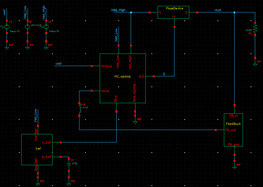
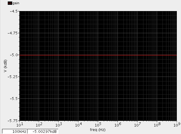
break the loop between resistors. connect this point and opamp's input by huge inductance for example 1G (to ensure operating point). pass ac source also by huge capacitor 1G
Shouldn't the inputs of the error amp be connected in the reversed direction to ensure that the regulating loop is stable?
Another way: the AC signal should be inserted into the input of negative input of AMP
Shouldn't the inputs of the error amp be connected in the reversed direction to ensure that the regulating loop is stable?
No, its correct, because the source follower does not invert the signal.
It's not clear which variant the comments are referring to.
For #3 I'd say it's not a source follower either, and the feedBack connection here is wrong.
Hey erik, can you tell me why I have seen a source follower in post#3? Because I can't.
Hi LvW, nor can I, that's what I told above. How should I know where you have seen a source follower in post#3? Must be a misunderstanding, I guess.
What, do you think, should be corrected?