Continue to Site

Welcome to EDAboard.com

Welcome to our site! EDAboard.com is an international Electronics Discussion Forum focused on EDA software, circuits, schematics, books, theory, papers, asic, pld, 8051, DSP, Network, RF, Analog Design, PCB, Service Manuals... and a whole lot more! To participate you need to register. Registration is free. Click here to register now.

How to reduce the flicker noise of bias circuit

Status
Not open for further replies.

xiaowenrun

Junior Member level 3
Joined
Dec 6, 2021
Messages
30
Helped
0
Reputation
0
Reaction score
0
Trophy points
6
Activity points
222
Hello
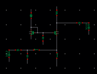
I am simulating a CG low-noise amplifier. And I found the flicker noise of the bias transistor dominates. How could it contribute more than the input transistor? The bias transistor is circled in the following picture. And how can I reduce its flicker noise?
Thanks
1663649824784.png
 

Attachments

  • 1663649788970.png
    1663649788970.png
    3.6 KB · Views: 124

You should increase area of the transistors(both bias and CG transistors). That is increase W and L while keeping W/L constant.

Bias transistor's flicker noise is increased by the amount of mirror ratio, that may be the reason why bias noise is dominant. Therefore, be sure reference current is not too small than CG current. In the expense of higher power consumption (due to increase in reference bias current), your noise should be better.
Thanks.
At first, I hoped that there would be some circuit skills to optimize this noise, but I had not found any.
 

If the gate bypass capacitor has no effect in the frequency range of interest, the bias transistor will contribute to overall noise anyway. Increase it.
 

You should increase area of the transistors(both bias and CG transistors). That is increase W and L while keeping W/L constant.

Bias transistor's flicker noise is increased by the amount of mirror ratio, that may be the reason why bias noise is dominant. Therefore, be sure reference current is not too small than CG current. In the expense of higher power consumption (due to increase in reference bias current), your noise should be better.
Thanks. I agree with you about the influence of transistor size on flicker noise. I don't think there is a direct link between the consumed current and flicker noise. You could reduce flicker noise by using a bias transistor with a larger width and a smaller mirror ratio. But the decrease in flicker noise is due to the increase in width rather than the increase in current. However, the growth of the current reduces the thermal noise.
--- Updated ---

If the gate bypass capacitor has no effect in the frequency range of interest, the bias transistor will contribute to overall noise anyway. Increase it.
Thanks. Yes, increasing the capacitor can reduce the contribution of the bias transistor. But at low frequency, its effect is too weak. Like at 20MHz.
 
Last edited:

Flicker noise is directly related to the current density in the transistor.
My simulations shows that I get minimum flicker noise when I use a bigger transistor supporting higher Id/Ic, but used at its minimum as possible Id/Ic current.
I found that this is valid for both, CMOS and BJTs..
 

Flicker noise is directly related to the current density in the transistor.
My simulations shows that I get minimum flicker noise when I use a bigger transistor supporting higher Id/Ic, but used at its minimum as possible Id/Ic current.
I found that this is valid for both, CMOS and BJTs..
How do you define current density?
So you are talking about BJT. I am not familiar with that. But in MOS, Id equals Is. So I do not understand how to apply the relationship between flicker noise and Id/Ic in MOS.
--- Updated ---

Did you check how apart is the device VDS voltage from its pinch-off voltage?
I guess you are wondering how flicker noise changes with the source-drain voltage. But I don't think that is a problem.
Cause in a bias circuit, the transistor is connected like a diode, and there is enough vds.
For the CG structure mentioned in this thread, the input transistor will also be set to work in saturation mode. And if its vds is changed. Its current and transconductance will change too. So as the noise transfer function. Thus, analyzing the influence of Vds on flicker noise merely is not easy.
 
Last edited:

Status
Not open for further replies.

Part and Inventory Search

Welcome to EDABoard.com

Sponsor

Back
Top