Continue to Site

Welcome to EDAboard.com

Welcome to our site! EDAboard.com is an international Electronics Discussion Forum focused on EDA software, circuits, schematics, books, theory, papers, asic, pld, 8051, DSP, Network, RF, Analog Design, PCB, Service Manuals... and a whole lot more! To participate you need to register. Registration is free. Click here to register now.

How to recover the clock without using PLL?

Status
Not open for further replies.
YOu need two delay circuits. One to produce double edge clock using XOR (any period <<<50% of T is ok since only leading edge is used to reduce jitter) show below.


The Decoder latch uses a 2nd time delay that is leading edge trigger and non-retrigerable for the duration of 3/4 T where T is the symbol time to latch input data to decode correct phase of clock. Then this second clock is used to decode state of input to recover the data.
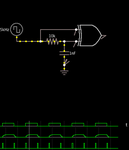
Screen shot 2012-07-28 at 1.56.30 PM.png
YOu can choose any Manchester protocol. Biø-M, Biø-S or Biø-I for mark, space or invert.
 
  • Like
Reactions: iVenky

    iVenky

    Points: 2
    Helpful Answer Positive Rating
YOu need two delay circuits. One to produce double edge clock using XOR (any period <<<50% of T is ok since only leading edge is used to reduce jitter) show below.


The Decoder latch uses a 2nd time delay that is leading edge trigger and non-retrigerable for the duration of 3/4 T where T is the symbol time to latch input data to decode correct phase of clock. Then this second clock is used to decode state of input to recover the data.
View attachment 77850
YOu can choose any Manchester protocol. Biø-M, Biø-S or Biø-I for mark, space or invert.

I see that you have included the first delay circuit. I would be really happy if you could tell me about the second delay circuit. How to have a circuit that is leading edge triggerable and non-triggerable for 3/4 T?

Thanks a lot.
 

YOu need two delay circuits. One to produce double edge clock using XOR (any period <<<50% of T is ok since only leading edge is used to reduce jitter) show below.


The Decoder latch uses a 2nd time delay that is leading edge trigger and non-retrigerable for the duration of 3/4 T where T is the symbol time to latch input data to decode correct phase of clock. Then this second clock is used to decode state of input to recover the data.
View attachment 77850
YOu can choose any Manchester protocol. Biø-M, Biø-S or Biø-I for mark, space or invert.

Hello sir. I am waiting for your reply.

Thanks a lot.
 

Status
Not open for further replies.

Part and Inventory Search

Welcome to EDABoard.com

Sponsor

Back
Top