gkini19
Newbie level 5
Hi All,
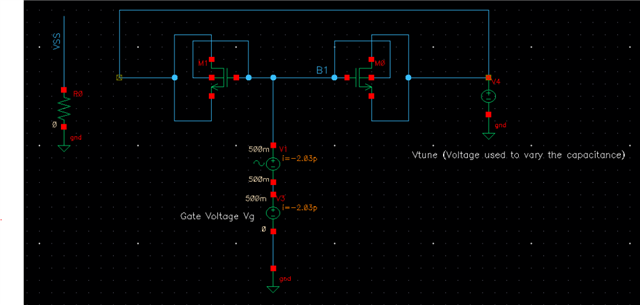
I am using the circuit shown below. I want to have a tuning range of 2-4 GHz for LC VCO. I want to use the varactor in this configuration.
My question:
1) How can I find the capacitance of the transistors used as a varactor? which analysis should I use and which plot will be useful?
2) To have a tuning range of 2 GHz how many stages of such Varactors should I have? is there a method or a way to choose this?
Thanks all in advance