Continue to Site

Welcome to EDAboard.com

Welcome to our site! EDAboard.com is an international Electronics Discussion Forum focused on EDA software, circuits, schematics, books, theory, papers, asic, pld, 8051, DSP, Network, RF, Analog Design, PCB, Service Manuals... and a whole lot more! To participate you need to register. Registration is free. Click here to register now.

How to increase the drive strength of a Amplifier model

Status
Not open for further replies.

henry kissinger

Member level 2
Joined
Nov 19, 2021
Messages
44
Helped
0
Reputation
0
Reaction score
0
Trophy points
6
Activity points
442
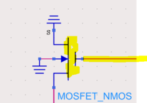
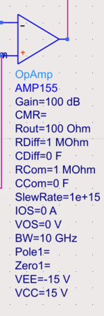
I am using a OP amp model from Keysight ADS.
How parameters I have to change in order to increase the drive strength of this circuit?
The issue I have right now is that the output of the Op Amp is not strong enough as expected due to the capacitance of the Oxide capacitance it connects to.
 

Attachments

  • 1665176117069.png
    1665176117069.png
    6.4 KB · Views: 100
  • 1665176021223.png
    1665176021223.png
    39.4 KB · Views: 107

Please show the circuit and the problem you are experiencing with it.
Below is the entire circuit, the Op Amp is generating a voltage to Vsink, which then connects to a gate of a NMOSFET.
When the Tox of the NMOSFET is 1e-7, the capacitance is small, so Vsink voltage profile is expected. (-15V->15V)
However for design reason, I need to have the Tox as 1e-9, but then the Op Amp is not strong enough to drive the Vsink because of the bigger oxide capacitance at the NMOSFET.
How should I modify the Op Amp (changing the parameters) to give expected Vsink at Tox=1e-9

1665185788312.png

1665185824248.png

1665185858453.png
 
Last edited:

The fictive "OP Amp" with 10 GHZ bandwidth and infinite slew rate is effectively working as square wave voltage source, limiting parameter is the large Rout of 100 ohm. Don't know which real components you want to model with the circuit. If you are looking for a real component, use a fast gate driver. As ideal driver, you can simply place a controlled voltage source, but with lower output resistance.
 

Vcvs and whatever R you like, appended?

For more of a simple current boost, a v=0 series source between amp and load, and a paralleled ccvs with (say) a=9 would give you a straight 20X drive increase without touching the guts.
 

You set op amp for 100 ohms output impedance. That's greater than an old-fashioned 741, looking at its internals (below). Notice resistor values of 25 & 50 ohms at its output stage. This means with a load of 500 ohms, voltage at load is dropped 5 to 10 percent automatically.

Similarly your 100 ohms has the effect of limiting current. Try a lesser value such as 10 ohms.

741 internals with load (falstad).png
 

Vcvs and whatever R you like, appended?

For more of a simple current boost, a v=0 series source between amp and load, and a paralleled ccvs with (say) a=9 would give you a straight 20X drive increase without touching the guts.
That should have been cccs... thanks, Chrome spell-guesser.
 

Status
Not open for further replies.

Part and Inventory Search

Welcome to EDABoard.com

Sponsor

Back
Top