Continue to Site

Welcome to EDAboard.com

Welcome to our site! EDAboard.com is an international Electronics Discussion Forum focused on EDA software, circuits, schematics, books, theory, papers, asic, pld, 8051, DSP, Network, RF, Analog Design, PCB, Service Manuals... and a whole lot more! To participate you need to register. Registration is free. Click here to register now.

How to get the dead zone of PFD in this figure?

Status
Not open for further replies.

leonken

Full Member level 3
Joined
Jun 12, 2004
Messages
169
Helped
0
Reputation
0
Reaction score
0
Trophy points
1,296
Activity points
1,437
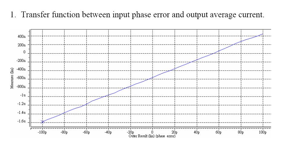
I found this figure. It is used to find out the dead zone of a PFD with CP in PLL design. The load of CP is a 1nF cap. This figure shows the dead zone vs. average current of 1nF cap.
My question is how to get the dead zone according to this figure?
Thanks.

3_1167341850.jpg
 

hi,
according to definition of ideal PFD, if there is no phase error, then no charge or average current will be deliveried to the capacitor. however, there exist dead zoon, this point(0,0) will be shifted.
so, from the figure, i think, the dead zone is about 52p,right?
 

The shift from origin is from CP mismatch
 

gualucci said:
The shift from origin is from CP mismatch

The figure is an answer of a homework.

They said:
Design a static phase-frequency detector (PFD) with a simple current pump
circuit to achieve the deadzone less 15ps. Suppose that the input frequency is 10MHz and the output filter is a capacitor of 1nF.

I'm confused that how to find out the deadzone is less than 15ps from this figure?
 

leonken said:
gualucci said:
The shift from origin is from CP mismatch

The figure is an answer of a homework.

They said:
Design a static phase-frequency detector (PFD) with a simple current pump
circuit to achieve the deadzone less 15ps. Suppose that the input frequency is 10MHz and the output filter is a capacitor of 1nF.

I'm confused that how to find out the deadzone is less than 15ps from this figure?

hi,
maybe you should pay aattaintion to the uint of x-axis.
jeff
 

The deadzone is a very old definition for ill deigned PFD-CHP designs. Please do not get confused by this.

Today the mimimum on time or minimum pulse width of either the UP or DW pulse is some factor higher than the current rise/fall time. In this case ther is a remaining nonlinearity in the delay to charge function. The plot showns some bumps at some point. That is because of coupling effects or supply interaction. The supply connection play a big rule in an otherwise clean design PFD-CHP design. For system level purposes you have to specify the dericvation from the nonlinear case. For proper designed combinations the derivation is modelled by an uncorrelated noise source. So the fractional loop and the other noise sources generate a delay distribution with gaussion shape. The derivation is then modelled as a additional noise generator.

The issue is that the "deadzone" concept lives in the books but these are 30 years back!
 

Status
Not open for further replies.

Part and Inventory Search

Welcome to EDABoard.com

Sponsor

Back
Top