Continue to Site

Welcome to EDAboard.com

Welcome to our site! EDAboard.com is an international Electronics Discussion Forum focused on EDA software, circuits, schematics, books, theory, papers, asic, pld, 8051, DSP, Network, RF, Analog Design, PCB, Service Manuals... and a whole lot more! To participate you need to register. Registration is free. Click here to register now.

How to derive the output equation for two series op-amps?

Status
Not open for further replies.

hobbskw

Junior Member level 3
Joined
Oct 19, 2021
Messages
25
Helped
1
Reputation
2
Reaction score
1
Trophy points
3
Activity points
197
Greetings,
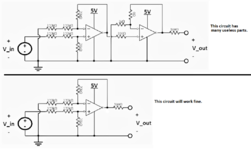
I am trying to figure out the overall gain of this circuit analytically. Simulations and experiments both show that it is 0.0832, but how do I go about calculating this by hand? I would greatly appreciate any help!
1655477255754.png
 

Clues :

1) Amps are considered (simple models) to have voltage outputs, eg. 0 ohms.
So that allows you to compute G of each stage and then multiply the two
stage G's to get overall G.

2) Because simple amp model has infinite internal G that implies, thru analysis,
that any amp with - fdbk implies the V+ and V- input amps are at same V.

3) Amp input Z at V+ and V- is infinite for simple model.

3) So starting with first amp V + = V_In x the R divider at its input, Then write Kirchoffs laws
and solve for Vout. Hint you know the current thru the two R's to ground at V- is
same as current thru fdbk R to V-, so computing Vout easy,
V- + I x Rfdbk = Vout = V+ + I x Rfdbk.

4) Second amp is also solved same as first amp.


Regards, Dana.
 

Hi,

The first one is built as a "difference amplifier".
The second one is just a buffer.

The whole circuit does not make much sense. The whole circuit could be replaced by two resistors (voltage divider)

But your calculation is correct. (my result 0.08333..)

Klaus
 

1655485938443.png


So virtual ground, in case of either inverting or non inverting, means the two inputs
are "virtually" at same voltage. This cause one to easily analyze opamp circuits as show in
prior post using this approximation.


Regards, Dana.
 

Your second transistor and its resistors are not needed since the output of the first opamp can produce the same output.
You need an opamp that has inputs that work down to the same voltage (0V) as its negative supply (0V).
 

Attachments

  • two opamps.png
    two opamps.png
    118.2 KB · Views: 144

as above, the 2nd one is not needed - the volts you measure are the lowest the op amp output can go to with no input signal - or input shorted ...

real opamps cannot go to zero ( or full rail )
 

In closing, here is an example of losing virtual ground due to opamp G falling
with increasing frequency. The Aol curve 3 db point typically 10 Hz, so the
virtual ground error starts there and OpAmp starts losing control of the
loop error. Levels off at 1 Mhz where internal OpAmp G has fallen to 1.

1655552659512.png


1655552892345.png


Regards, Dana.
 

Status
Not open for further replies.

Part and Inventory Search

Welcome to EDABoard.com

Sponsor

Back
Top