Continue to Site

Welcome to EDAboard.com

Welcome to our site! EDAboard.com is an international Electronics Discussion Forum focused on EDA software, circuits, schematics, books, theory, papers, asic, pld, 8051, DSP, Network, RF, Analog Design, PCB, Service Manuals... and a whole lot more! To participate you need to register. Registration is free. Click here to register now.

How to connect 3 different lights (indication) for 3 different deptts. in such a way

Status
Not open for further replies.

danishdeshmuk

Advanced Member level 1
Joined
Aug 17, 2011
Messages
426
Helped
35
Reputation
70
Reaction score
35
Trophy points
1,308
Activity points
4,001
How to connect 3 different lights (indication) for 3 different deptts. in such a way that when alarm button is pressed in the respective deptt (department) the respective light turns on ?

Note : All the Alarm buttons are on-off switches and they are all (of every department) connected to each other ....

thanks
 

The simplest way would be to wire the circuit for each "deptt" separately, just like a separate switch for each light bulb in your house. This is so obvious that you probably have something different in mind.

Can you explain in more detail what you want to do? What exactly do you mean by saying that the switches are all connected together?
 

means there are no separate connections , the phase is common in each of the alarm buttons
 

Since you don't want to use separate lines for each switch, I don't think there's a way to do what you want simply by some trick of wiring. It will have to involve some electronics to detect which switch is being pressed.

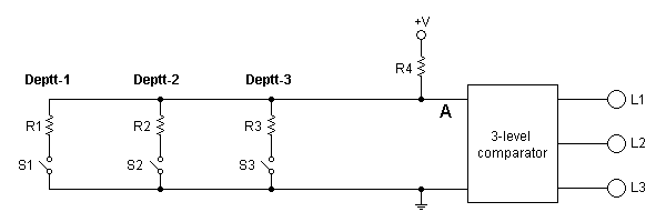
I'm still not perfectly sure I understand what it is you're trying to do. But if I got it correctly, the following scheme should provide one possible solution:

21_1337800506.png


R1, R2, R3 must have different values. When S1, S2 or S3 is pressed, each corresponding resistor forms a voltage divider with R4 and a fraction of the supply voltage +V is presented at point A. Since R1, R2, R3 are all different, each switch press presents a different voltage at A. The 3-level comparator detects the corresponding voltage for each switch and turns one output on. The comparator could be an LM3914 working in dot mode.

Another possible approach is to connect all 3 switches in series, with each switch paralleled by a resistor, the resistors again being of different values.
 
How to connect 3 different lights (indication) for 3 different deptts. in such a way that when alarm button is pressed in the respective deptt (department) the respective light turns on ?

Note : All the Alarm buttons are on-off switches and they are all (of every department) connected to each other ....

thanks

See this my friend you only need two wires and can add many "deptts"

https://www.edaboard.com/threads/253276/
 

what about the circuit that pjdd has provided ? What's the problem and lacking in it ?

---------- Post added at 21:34 ---------- Previous post was at 21:31 ----------

the problem is that we have to use AC 220 V supply and AC 220 V almost 100 watts bulbs each .....
the panel containing bulbs would be mounted on the wall (almost 25 to 30 feets above the ground) of the hall
 

what about the circuit that pjdd has provided ? What's the problem and lacking in it ?


Of course nothing, you can use it. This is similar solution, and his is even simpler because he use LM3914.

the problem is that we have to use AC 220 V supply and AC 220 V almost 100 watts bulbs each .....
the panel containing bulbs would be mounted on the wall (almost 25 to 30 feets above the ground) of the hall

You can switch what you whant.
 

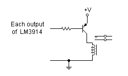
To control a mains load like a 100W bulb, you will have to use each output of the LM3914 or the microcontroller to drive a relay. The relay can be electro-mechanical or solid-state. If you want to use a conventional electro-mechanical relay, the LM3914 (or uC) output has to be buffered by a transistor. Like this -

88_1337971940.png


As tpetar said, the working principle of his circuit and mine are the same. The difference is in the device used to detect the different input levels.
 

kindly tell me the no. & type of transistor , value of resistor & the power of the relay ?
 

Status
Not open for further replies.

Part and Inventory Search

Welcome to EDABoard.com

Sponsor

Back
Top