tpetar
Advanced Member level 7
- Joined
- Sep 27, 2010
- Messages
- 6,417
- Helped
- 1,713
- Reputation
- 3,456
- Reaction score
- 1,673
- Trophy points
- 1,393
- Location
- Pancevo-Belgrade, Serbia
- Activity points
- 37,363
Connecting multiple tact switches on a single input pin of a microcontroller
https://embedded-lab.com/blog/?p=4040
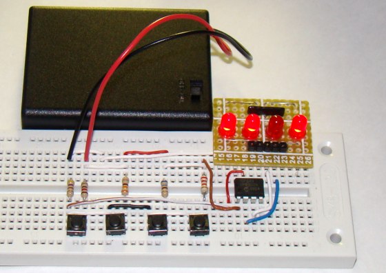
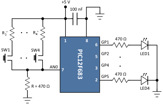
Normally one tact switch requires one digital input pin of a microcontroller. Some designs implement keypad style multiplexing to get multiple switches on fewer inputs. However, there exist other techniques that allow you to connect many switches on a single input pin of a microcontroller. This tutorial demonstrates one such technique as applied to PIC12F683 microcontroller. In this example, there are four LEDs and four tact switches connected to the PIC12F683 microcontroller. While each LED is controlled through an individual I/O pin, the four switches are connected to one ADC input pin of the PIC12F683 microcontroller.
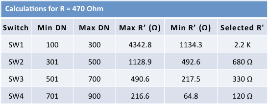
A technique of interfacing multiple tact switches using a single ADC input pin was demonstrated using the PIC12F683 microcontroller. A digital input from four tact switches were individually read through the AN0 ADC channel and displayed it back on an LED. While this technique saves input pins and reduces the size, one downside of the design is detecting combination of switches. The calculations of R’ resistors become more complex in such a case. The resistor values must be chosen very carefully so that the voltage resulting from a switch combination is unique.
.
.
.
.
Very interested thinking and approach...
https://embedded-lab.com/blog/?p=4040
Normally one tact switch requires one digital input pin of a microcontroller. Some designs implement keypad style multiplexing to get multiple switches on fewer inputs. However, there exist other techniques that allow you to connect many switches on a single input pin of a microcontroller. This tutorial demonstrates one such technique as applied to PIC12F683 microcontroller. In this example, there are four LEDs and four tact switches connected to the PIC12F683 microcontroller. While each LED is controlled through an individual I/O pin, the four switches are connected to one ADC input pin of the PIC12F683 microcontroller.
A technique of interfacing multiple tact switches using a single ADC input pin was demonstrated using the PIC12F683 microcontroller. A digital input from four tact switches were individually read through the AN0 ADC channel and displayed it back on an LED. While this technique saves input pins and reduces the size, one downside of the design is detecting combination of switches. The calculations of R’ resistors become more complex in such a case. The resistor values must be chosen very carefully so that the voltage resulting from a switch combination is unique.
Code:
/*
  Multiple digital inputs from a single I/O pin
  Copyright@Rajendra Bhatt
  Nov 15, 2011
*/

// Define LEDs
sbit LED1 at GP1_bit;
sbit LED2 at GP2_bit;
sbit LED3 at GP4_bit;
sbit LED4 at GP5_bit;

void Delay_250ms(){
 Delay_ms(250);
}

unsigned int ADC_Value;
void main() {
  CMCON0 = 7;  // Disable Comparators
  TRISIO = 0b00001001;  // All Outputs, except GP0 and GP3
  ANSEL = 0x01; // GP0 analog i/p

  do {
   ADC_Value = ADC_Read(0);
   if(ADC_Value > 700) { // SW4
     LED4 = ~LED4;
     Delay_250ms();
   }
   if(ADC_Value > 500 && ADC_Value < 700) { // SW3
     LED3 = ~LED3;
     Delay_250ms();
   }
   if(ADC_Value > 300 && ADC_Value < 500) { // SW2
     LED2 = ~LED2;
     Delay_250ms();
   }
   if(ADC_Value > 100 && ADC_Value < 300) { // SW1
     LED1 = ~LED1;
     Delay_250ms();
   }
  } while(1);
}
.
.
.
.
Very interested thinking and approach...
Last edited: