Continue to Site

Welcome to EDAboard.com

Welcome to our site! EDAboard.com is an international Electronics Discussion Forum focused on EDA software, circuits, schematics, books, theory, papers, asic, pld, 8051, DSP, Network, RF, Analog Design, PCB, Service Manuals... and a whole lot more! To participate you need to register. Registration is free. Click here to register now.

how this oscillator works?

jin2022

Newbie
Joined
May 16, 2022
Messages
5
Helped
0
Reputation
0
Reaction score
0
Trophy points
1
Activity points
40
hi,friends,
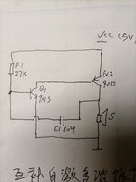
how this circuit oscillate?
at first , vcc charge c1 through r1 and speaker, makes left side voltage of c1 goes up, which makes q1 start to conduct. this makes q2 to conduct.which makes right side voltage of C1 goes up.
and then? how does the circuit oscillate?I'm puzzled. I need your help.
thx.
 

Attachments

  • IMG_20230514_194647.jpg
    IMG_20230514_194647.jpg
    2.6 MB · Views: 80
As you describe, the capacitor discharges to turn on Q1 briefly, turning on Q2.

The capacitor discharges entirely. At that moment Q1 shuts off.
Q2 shuts off.

The speaker then has 0V across it. Rightmost end of capacitor is pulled to 0V.

The charging process begins again.

-=-=-=-=-=-=-=-=-=-=-=-=-=-=-=-=-=-=-=-=-=-=-

Falstad's animated interactive simulator taught me the above. It's ideal for examining behavior of circuits such as this.
Electrons (or rather current bundles) are depicted moving through wires, to portray direction and intensity.

Free to download and use at:

falstad.com/circuit
 
It's seems like two Bipolar Junction Transistors in Darlington configuration, but in this example one has npn transistor and the other has pnp junction. Using this type of circuit you can get a greater current gain with a low current base.
Its name is Sziklai pair.
 
As you describe, the capacitor discharges to turn on Q1 briefly, turning on Q2.

The capacitor discharges entirely. At that moment Q1 shuts off.
Q2 shuts off.

The speaker then has 0V across it. Rightmost end of capacitor is pulled to 0V.

The charging process begins again.
I mean the cap charges to turn on Q1and Q2.
it seems when the cap charged entirely (Q2 become saturation), at that moment , collector voltage of Q2starts to drop, by cap couple ing,q1 base voltage start to drop, this makes q2collector voltage go low again,this makes posative feedback,until q2collector voltage goes to 0v.
what I don't understand is: why q2 collector start s go down as soon as it goes saturation?(from my reading)
 
I think the circuit is just a current amplifier to amplify the AC signal coming into Q1 base and then delivers this amplified current to a speaker. Vcc is used for polarization of both BJTs.

I have simulated in QUCS a simular circuit.
1686226706969.png

The AC is just a simple pulse of 0.4mA of amplitude and 1ms of width. Results are below:

1686227413253.png

You can observe that input current is amplified by a factor 0.0592/0.0004 = 148, not too high due to 50Ohm load used, but this explains the amplification of current.
1686227434264.png
 
I think the circuit is just a current amplifier to amplify the AC signal coming into Q1 base and then delivers this amplified current to a speaker. Vcc is used for polarization of both BJTs.

I have simulated in QUCS a simular circuit.
View attachment 183236
The AC is just a simple pulse of 0.4mA of amplitude and 1ms of width. Results are below:

View attachment 183241
You can observe that input current is amplified by a factor 0.0592/0.0004 = 148, not too high due to 50Ohm load used, but this explains the amplification of current.
View attachment 183242
I think you're right. but now no input current, and it can be an oscillator.
 
Collector current flows. Then:

1) Some of this current goes through the load and some current goes through the capacitor.

2) Capacitor current carries pulse to transistor network turning transistors On.

3) Soon capacitor blocks DC, thus blocks current through it.

4) Transistors shut off. Load voltage drops to zero, pulling righthand wire of capacitor to zero.

5) Capacitor starts to charge again.

----------------------------------------

Notice the lefthand wire at the cap is a fraction of a volt, changing slightly in order to turn NPN bias On & Off. Likewise capacitor charge goes up and down a fraction of a volt.

This circuit's action has delicate balances going on, and component values need experimentation to make it oscillate.
 

LaTeX Commands Quick-Menu:

Similar threads

Part and Inventory Search

Welcome to EDABoard.com

Sponsor

Back
Top