Continue to Site

Welcome to EDAboard.com

Welcome to our site! EDAboard.com is an international Electronics Discussion Forum focused on EDA software, circuits, schematics, books, theory, papers, asic, pld, 8051, DSP, Network, RF, Analog Design, PCB, Service Manuals... and a whole lot more! To participate you need to register. Registration is free. Click here to register now.

how this increase Q factor?

Status
Not open for further replies.

rezaee

Full Member level 2
Joined
Jul 3, 2009
Messages
129
Helped
4
Reputation
8
Reaction score
1
Trophy points
1,298
Activity points
2,117
Hello

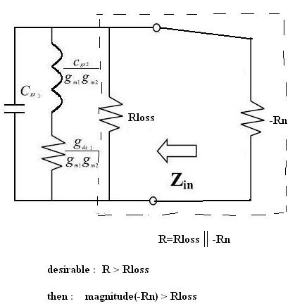
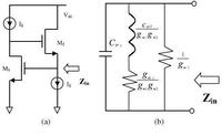
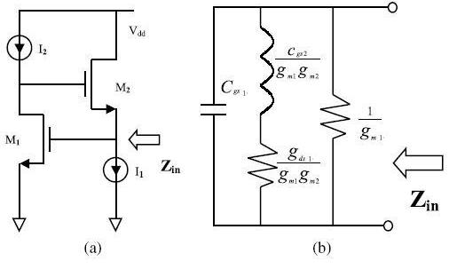
the below picture show an activer inductor basic circuit (figure "a" ) and its equal small signal model (figure "b" ), and the Q factor is defined Real(Zin)/Image(Zin)


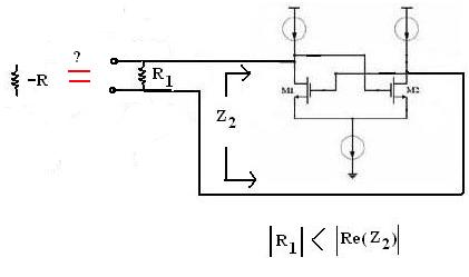
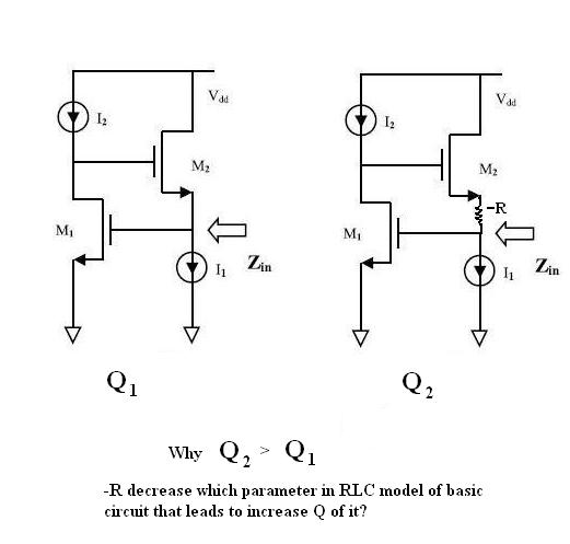
the below procedure can increase the value of Q-factor, Is it possible describe to me that how this procedure can increase Q factor of basic circuit?
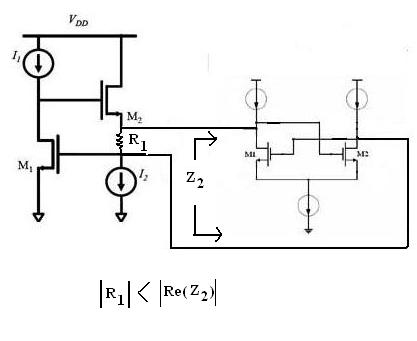
64_1309536276.jpg
 

Hi,

I've not analyzed accurately the impedance Z2 presented by the pair, but it can be seen that it presents a negative conductance (equivalently, a negative resistance).
Such an element increase Q because it increases parallel resistance (or make the circuit unstable if the total G is still negative, i.e. Q goes beyond infinity!).
Regards

Z
 
Last edited:

Hi zorro

yes the pair has negative resistance and its value is more than R1,
could you please describe me more? what do you mean "Such an element increase Q because it increases parallel resistance" ?
 

Hi rezaee,

r1 || r2 = 1/(1/r1 + 1/r2)

If r1 is positive and r2 is negative, but |r2|>r1, the denominator of the above expression is positive but lower than 1/r1.
Then the parallel is higher than r1.

In a parallel RL or RC, Q=R/X (X is reactance). So, increasing R increases Q.
Regards

Z
 
  • Like
Reactions: rezaee

    rezaee

    Points: 2
    Helpful Answer Positive Rating
Hi zorro,

thanks for your reply

Is you mean that just the role of r2 is increasing r1? on the other hand can I delet the pair and increasing r1 value instead of it?

Is you mean from parallel RL or RC the equal circuit can be replaced instead of r1 and its parallel pair?
if the answer is yes then for what reason placement a parallel RC between source of M2 and gate of M1 can improve the Q of basic circuit?

Regards
 

In a parallel RL or RC, Q=R/X (X is reactance). So, increasing R increases Q.

I was all set to reply skeptically at this, since I'm more familiar with topologies where increasing R reduces Q. That is, with series RLC resonant circuits. Because greater R causes greater damping.

So I looked it up.

Sure enough, a Wikipedia article clarifies that the opposite is the case with a parallel RLC as compared to the series.

RLC circuit - Wikipedia, the free encyclopedia

"A wide band, low Q circuit in one topology will become a narrow band, high Q circuit in the other topology when constructed from components with identical values."

So you are correct.
 

I think, it is not necessary to further discuss the basic fact that a negative resistance in parallel to a positive one will increase the total damping resistance of a parallel tank circuit - provided that the magnitude of |-R| remains larger than the positive part (because of stability reasons).
(Similarly, a series resonant circuit with a series loss resistor will get less damping by a series connection of -R).
More important is the question WHY the right hand part of the circuit can act as a system that has a negative input resistance.

I think, a more general explanation can be given by recognizing that negative resistances are created by applying positive feedback. As clearly can be seen, the output of the left hand transistor (in inverting common source configuration) is connected to the input of another transistor in the same configuration and fed back to the first one - a classical positive feedback configuration.
A mathematical treatment of the circuit (calculation of input resistance) will depend on the dimensioning of the whole circuit (current sources, FET's).

Remark:
I think it is possible to compare both parts of the circuit: Both realize a closed-loop operation.
The left hand part (the original circuit) also provides a closed-loop connection between both FETs.
However, here we have negative feedback because the right hand transistor operates in non-inverting configuration (in contrast to the right hand part).
 
Last edited:
  • Like
Reactions: rezaee

    rezaee

    Points: 2
    Helpful Answer Positive Rating
let me ask my question in another form

the cross-coupled pair has negative resistance, yes it is true, but when it is in parallel with a resistor that the value of it is positive and smaller than the magnitude of Real{Zcross-coupled}, then the Their equivalent circuit has not negative resistance :

46_1309602241.jpg


now we assume the equivalent circuit of cross-coupled pair and the small resistor parallel with it act as a negative resistance, why it increase Q of basic circuit?


rezaee, in the upper diagram it is not correct that the R1 belongs to the negative-resistance circuit.
Therefore, the lower diagram also isn't correct as it shows a negative resistor.

Please consider that the non-ideal active inductor (with 2 FETs and 2 current sources) has a resistive part that causes losses.
These losses cannot be represented as a single resistor in the circuit diagram (as you did in the second diagram, yesterday). However, the losses can be derived from the passive equivalent circuit diagram and can be named "Rloss".
These losses can be reduced by connecting another active circuit that has a negative input resistance -Rn.
(Loss reduction in a parallel circuit means: Increase of R).
However, both elements together (Rloss||(-Rn) ) must not realize a negative parallel combination.
(Therefore: Rloss<|-Rn| )
In summary - the original circuit remains as it is - however, it is extended by another active circuit that can improve the resulting Q of the inductor.
The loss resistance Rloss in parallel with the negative resistance -Rn can be explicitely shown in the eqivalent circuit diagram only.
 
Last edited:
  • Like
Reactions: rezaee

    rezaee

    Points: 2
    Helpful Answer Positive Rating
I think you mean is :

95_1309617671.jpg


now 2 question:
1-why the -Rn (cross-coupled) between source of M2 and gate of M1 placed in parallel with Rloss in the passive element model of the basic circuit(2mosfet and 2 current source) ?

2-when I put cross-coupled pair between source of M2 and gate of M1 I need to put a small positive resistor parallel with it if I dont place it my simulation result be bad. why is this?
 

I think you mean is :
.....................
now 2 question:
1-why the -Rn (cross-coupled) between source of M2 and gate of M1 placed in parallel with Rloss in the passive element model of the basic circuit(2mosfet and 2 current source) ?

2-when I put cross-coupled pair between source of M2 and gate of M1 I need to put a small positive resistor parallel with it if I dont place it my simulation result be bad. why is this?

To 1.) Yes, that's what I mean - assuming that the losses due to the parallel resistor in the equivalent diagram dominate over the series losses. However, this assumption is in accordance with the information contained in your first posting (Q increase).

To 2.) This could be a confirmation of the fact that - without this additional "small" resistor (what does this mean???) - the negative resistance would not be large enough (requirement: Rpos < |Rn|)
________________
Question: From your measurements/simulations do you have some parts values for the equivalent circuit?

Second question (for clarification): What is R1 in your first posting? Is it a lumped element (resistor) that is actually existent in the circuit? Or, is it something like an equivalent resistor that, according to my understanding, mst be shown in an equivalent diagram only?
 
Last edited:

Question: From your measurements/simulations do you have some parts values for the equivalent circuit?

I simulate the active circuit no the equivalent passive circuit.

Second question (for clarification): What is R1 in your first posting? Is it a lumped element (resistor) that is actually existent in the circuit? Or, is it something like an equivalent resistor that, according to my understanding, mst be shown in an equivalent diagram only?

R1 is a lumped element resistor and isnt equivalent resistor
 

I simulate the active circuit no the equivalent passive circuit.

Yes, that's clear to me. Otherwise, I would not ask if you values for the passive equivalent circuit.
But my question is, if you are able to derive from the active circuit behaviour some information on the equivalent circuit? For example, what is the desired L value at what frequency? Are series or parallel losses dominant?

R1 is a lumped element resistor and isnt equivalent resistor

OK, that's new to me. In this case, I see two options:
case (1): R1||(-Rn) > 0 : In this case (-Rn) causes an increase of the total resistance. The same effect should be possible by increasing R1 directly (without the neg. resistance circuit). However, I don`t expect a Q improvement by doing this.
case (2): R1||(-Rn) < 0 : The resulting resistance is negative; I can imagine that this, indeed, could lead to a Q improvement.

As a first step, perhaps you should (a) realize the neg. resistance during simulation simply as (-R) - instead of using the active circuitry - and (b) play a little with the value of R1 and Rn to see the difference between cases (1) and (2).
 

my question is, if you are able to derive from the active circuit behaviour some information on the equivalent circuit? For example, what is the desired L value at what frequency? Are series or parallel losses dominant?

at #1 in the first picture you can see the equivalent circuit elements relation with transistors parameters, is not sufficient for estimation?

OK, that's new to me. In this case, I see two options:
case (1): R1||(-Rn) > 0 : In this case (-Rn) causes an increase of the total resistance. The same effect should be possible by increasing R1 directly (without the neg. resistance circuit). However, I don`t expect a Q improvement by doing this.
case (2): R1||(-Rn) < 0 : The resulting resistance is negative; I can imagine that this, indeed, could lead to a Q improvement.


in my simulation ,case (1) is happend, beacuse R1=+12ohm and negative resistance ( real part of cross-coupled pair input impedance at the frequency that the Q is maximum ) is -Rn=-180ohm but when I delet cross-coupled pair and just use R1 with larger value, the simulation result isnt same and is worse even in compare with basic circuit (2mosfet&2current source)

As a first step, perhaps you should (a) realize the neg. resistance during simulation simply as (-R) - instead of using the active circuitry - and (b) play a little with the value of R1 and Rn to see the difference between cases (1) and (2).

I did this idea before delet active circuit (cross-coupled pair) and just use a resistor (lumped element) and sweep its for example between -50ohm and +50ohm the result show me that increasing R1 to positive value degrade Q but decreasing R1 value from 0 to negative value increase Q and just in a special negative value of R1 the Q is maximum.
but it is different with the use of Case (1)!!
 

at #1 in the first picture you can see the equivalent circuit elements relation with transistors parameters, is not sufficient for estimation?

No, it is not. Some information of the VALUES are interesting - for example, to know if the series or the parallel losses are dominant. This is necessary for explaining the effect of Q increase (as desired by you).


in my simulation ,case (1) is happend, beacuse R1=+12ohm and negative resistance ( real part of cross-coupled pair input impedance at the frequency that the Q is maximum ) is -Rn=-180ohm

Are you sure about Rn=-180 ohms for the cross-coupled pair?

I did this idea before delet active circuit (cross-coupled pair) and just use a resistor (lumped element) and sweep its for example between -50ohm and +50ohm the result show me that increasing R1 to positive value degrade Q but decreasing R1 value from 0 to negative value increase Q and just in a special negative value of R1 the Q is maximum.
but it is different with the use of Case (1)!!


...special negative value? What value?
 

No, it is not. Some information of the VALUES are interesting - for example, to know if the series or the parallel losses are dominant. This is necessary for explaining the effect of Q increase (as desired by you).

series is gds1/(gm1gm2) and parallel is 1/gm1 it seems that series has smaller value from the parallel losses.

Are you sure about Rn=-180 ohms for the cross-coupled pair?

I did S-parameter simulation in ADS and activate Z parameter and with simulation the cross-coupled pair I see the real part of Z(1,1) is -180

...special negative value? What value?

near -18ohm
 

series is gds1/(gm1gm2) and parallel is 1/gm1 it seems that series has smaller value from the parallel losses.

It will not be surprising if the series loss resistance is smaller than the parallel loss resistance. However, this does not mean that the parallel losses dominate. In contrary - a large parallel resistor (like a small series resistor) causes comparable small losses.

I did S-parameter simulation in ADS and activate Z parameter and with simulation the cross-coupled pair I see the real part of Z(1,1) is -180

I am a bit sceptical about the exactness of this value (see below)

...special negative value? What value?
near -18ohm


From this I conclude that a negative resistance R1=-|Rn| (R1 is the resistor as shown in the active L circuitry) can enhance the Q value of the active inductor.
This seems to be an indication that series losses dominate over parallel losses.
 

Some additional remarks:
* Regarding my doubts related to the value of -180 ohms: In case you have performed the simulation separately (cross-coupled pair not connected to the L-circuit) the operating conditions have been changed - if compared with the final configuration (both circuits connected).
* Since I have asked for values of the equivalent circuit: Evaluate the function Zin=f(frequency). This function should exhibit the desired inductive behaviour for medium frequencies, however for small frequencies there must be a fixed value that gives you an indication for the series loss resistance (assuming that the shown equivalent circuit diagram can be applied).
 

It will not be surprising if the series loss resistance is smaller than the parallel loss resistance. However, this does not mean that the parallel losses dominate. In contrary - a large parallel resistor (like a small series resistor) causes comparable small losses.

yes I know for increase Q I must increase parallel R and decrease series R with inductor ( in passive model )

I am a bit sceptical about the exactness of this value

why you have sceptical?

From this I conclude that a negative resistance R1=-|Rn| (R1 is the resistor as shown in the active L circuitry) can enhance the Q value of the active inductor.

yes your conclusion is correct but for what theory reason it happened?
and attention ,your conclusion is true but when I locate a single lumped element resistor in active L circuitry while the circuit that gives me good result is second photo in #1 that has 2 additional parts ( a lumped element resistor and a cross coupled pair ) that acts as a positive resistance no negative resistance beacuse magnitude of cross-coupled pair negative resistance is larger than lumped element resistor.

additional remarks:
Zin that acts as a L in basic circuit (2mosfet&2current source) is seen between ground and gate of M1, and according to this, equivalent circuit was drived. but additional circuits ( lumped element resistor and cross-coupled pair) is located between source of M2 and gate of M1 , then are not in parallel with Rp in equivalent circuit.

* Regarding my doubts related to the value of -180 ohms: In case you have performed the simulation separately (cross-coupled pair not connected to the L-circuit) the operating conditions have been changed - if compared with the final configuration (both circuits connected).

yes i simulate it separately but I think I can use decoupling capacitor
 

rezaee, now we have arrived at posting #19 - and I think it's time to summarize:
1.) You have a basic active circuit to simulate (approximately) an inductor (without R1). You also have a passive equivalent circuit with elements L, C, Rseries, Rpar.
You can simulate both and compare both function Z(s). From the comparison, it should be possible to derive (at least approximately) all values of the passive circuit.

2.) As you have discovered, a negative additional resistor ( let's designate as -|Rq|, location as shown by you) can improve the Q of the inductor. This indicates that the series losses are dominant because -|Rq| acts as a series resistor.

- As a first step you have investigated a parallel connection -|Rq|=R1||(-Rn). However, this approach did not give the desired improvement because you couldn't realize a total negative value (the magnitude |-Rn| was to large).
- Therefore, it is logical now to realize the required negative resistance -|Rq| either by the cross-coupled pair only (without R1) or as a series connection of an ohmic resitor R1 and -|Rn|.
- The second case may be necessary if it is not possible to realize the small value of -18 ohms (as mentioned by you) with the cross-coupled pair only.
- That means, realize this series connection within the L-circuit and try different values for R1 until you find the optimum.
 

Status
Not open for further replies.

Part and Inventory Search

Welcome to EDABoard.com

Sponsor

Back
Top