Continue to Site
Follow along with the video below to see how to install our site as a web app on your home screen.
Note: This feature may not be available in some browsers.
Later I will repost solution.
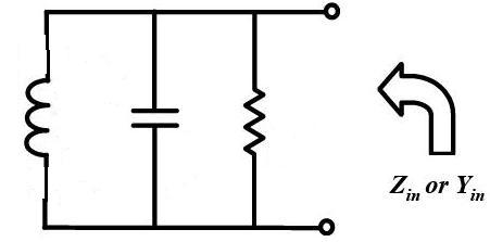
Q of Resonator does not depend on frequency.can anyone help me that how is it possible for me to calculate Q-factor of attached circuit
and draw it vs frequency in ADS simulator?
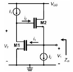
Which do you want to evaluate, Q of inductor or Q of resonator ?The circuit that I attached in #1 acts as an active inductor now I want to calculate the Q-factor of this,
but I dont know how I can do it?
Correct if it is Q of inductor.I read if we have an impedance like Zin=a+bj the Q factor is equal to b/a I dont know is it correct or no?
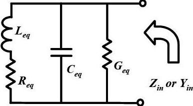
Again which do you want to evaluate, Q of inductor or Q of resonator ?definition of Q-factor for pure parallel RLC is different from the definition of Q-factor at the attached circuit?
for this circuit how I can write formulation of the Q-factor?
The circuit that I attached in #1 acts as an active inductor now I want to calculate the Q-factor of this, but I dont know how I can do it?
You are still confusing Q of resonator and Q of inductor.
Again surely read my links.
@pancho_hideboo: my problem is for this circuit(active inductor) that should I use resonator Q or inductor Q!!!?
@LvW: whats your idea? for this circuit(basic gyrator-C active inductor) which Q is important and which of them I should calculate and simulate?
Return "No" multiplied by hundred to you.No,You are still confusing Q of resonator and Q of inductor.
Again surely read my links.
w0*C/G is Q of parallel RLC resonator not Q of inductor.@ pancho-hideboo: I mean from pure parallel RLC is:
I want to calculate equation of Q for this active inductor circuit and also do simulation the Q of it with ADS.
You have to evaluate Q of inductor.@pancho_hideboo: my problem is for this circuit(active inductor) that should I use resonator Q or inductor Q!!!?
The Designer's Guide Community Forum - Negative Impedance seeing Vdd node of InvertersCorrect if it is Q of inductor.I read if we have an impedance like Zin=a+bj the Q factor is equal to b/a I dont know is it correct or no?

