Continue to Site

Welcome to EDAboard.com

Welcome to our site! EDAboard.com is an international Electronics Discussion Forum focused on EDA software, circuits, schematics, books, theory, papers, asic, pld, 8051, DSP, Network, RF, Analog Design, PCB, Service Manuals... and a whole lot more! To participate you need to register. Registration is free. Click here to register now.

[SOLVED] How Can I generate clock pulses for 50Hz square wave inverter using TMR2 and PR2

Status
Not open for further replies.
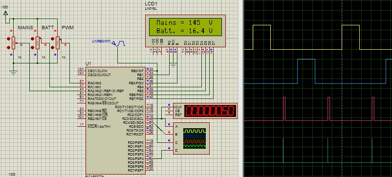
add a LCD voltmeter with another indication. I used a voltmeter on LCD. Also I've solved the problem. But still there is something tinny mistakes.
 

6528100700_1393802317.jpg
 

Attachments

  • inv.rar
    1,001 KB · Views: 225
I have to add phase-angel control for charging, input switches, LEDs indicators, relay control, advanced LCD menu, current sensing, overload protection, over/under mains voltage protection and maybe power factor correction etc.
 

Timer1 is sufficient for this purpose alone. Save timer2 for other timing purposes.
Code:
 #define   Clock1   RC5_bit
  #define   Clock2   RC6_bit
 char flag;
sbit flag1 at flag.B0;
sbit phase at flag.B1;
void interrupt()
{
    if(CCP1IF_bit)
    {
    if(flag1)
     {
      Clock1 = 0;
      Clock2 = 0;
      flag1=0;
      CCPR1L = 0xA8; // I/2 period
      CCPR1H = 0x02;
      }
    else
     {
     if (phase)
     {
      Clock1 = 1;
      phase=0;
      }
      else
      {
         Clock2 = 1;
         phase=1;
       }
         CCPR1L = 0xA8; //ON-time, PWM
         CCPR1H = 0x01;
      TMR1H = 0x00;//Clear  timer1
      TMR1L = 0x00;
      flag1=1;
    }
     CCP1IF_bit = 0;// clear flag
} // ISR...
 }
void PORT_Init(void)
{
   TRISC = 0x00; // PORTC output
   PORTC = 0x00; // all zero
}
void main()
{
   PORT_Init(void);
   // compare module settings...
   CCP1CON = 0b00001010;// trigger special event
   CCP1IE_bit = 1;
   CCPR1L = 0xA8;
   CCPR1H = 0x01;
      TMR1IF_bit = 0;
   GIE_bit = 1;
   PEIE_bit = 1;
   T1CON = 0x01;
       flag1=1;
   while(1)
    {
   }
}


Hi,
I am searching square wave code for inverter. I saw your video clips its working smoothly & very finely. You don't mind can you share only the PWM output section code (include the PWM variable)???? please don't say "no"...........

you can mail me: abrarjahinantor@yahoo.com

Thanks.

- - - Updated - - -

Code:
#define   Clock1   RC5_bit
#define   Clock2   RC6_bit
unsigned short flag=0;
void interrupt()
{
    if(CCP1IF_bit)
    {
       CCP1IF_bit = 0;// clear flag
       Clock1 = 0;
       Clock2 = 0;
    }
    if(TMR2IF_bit)
    {
      TMR2IF_bit = 0;//clear flag
      TMR1H = 0x00;//Clear  timer1
      TMR1L = 0x00;

      if(flag)
      {
      Clock1 = 1;
      flag=~flag;
      }
     else
      {
      Clock2 = 1;
      flag=~flag;
      }
    }

} // ISR...

void PORT_Init(void)
{
   TRISA = 0xFF; // PORTA input
   TRISB = 0b00000001; // PORTB output except RB0 & RB1
   PORTB = 0x00; // all zero
   TRISC = 0b00001000; // PORTC output
   PORTC = 0x00; // all zero
}


void main()
{
   PORT_Init(void);

   // Timer2 settings for 7ms interrupt
   T2CON = 0x36;
   PR2 = 223; // 10 ms time
   TMR2IE_bit = 1;
   INTCON = 0xC0;

   // compare module settings...
   CCP1CON = 0b00001011;// trigger special event
   CCP1IE_bit = 1;
   CCPR1L = 0xA8;
   CCPR1H = 0x31;
   //timer 1 settings...
   T1CON = 0x01;
   TMR1IF_bit = 0;

   while(1)
   {

   }  // while

   }


:-( :-( :-( :-( :-( :-( :-( :-( :-( :-( :-( :-( :-(
I converted you code into PicBasic Pro. but the problem is that the result is nothing. Can you tell me where I am wrong???

Code:
DEFINE OSC 10
   TRISB = 0; // PORTB output except RB0 & RB1
   PORTB = 0; // all zero
   TRISC = 0; // PORTC output
   PORTC = 0; // all zero
ON INTERRUPT GOTO UPDATE

FLAG VAR BIT : FLAG = 0
PWM1 VAR PORTC.5
PWM2 VAR PORTC.6

SETUP:
T2CON = $36
PR2 = 223
PIE1.1 = 1    'TMR2IE
INTCON = $C0
CCP1CON = %00001011
PIE1.2 = 1    'CCP1IE     
CCPR1L = $A8
CCPR1H = $31
T1CON = $01
PIR1.0 = 0    'TMR1IF

START:           'ENDLESS LOOP

GOTO START

DISABLE
UPDATE:
IF PIR1.5 = 1 THEN      'CCP1IF
	PWM1 = 0
	PWM2 = 0
	PIR1.5 = 0          'CCP1IF
ENDIF
IF PIR1.1 = 1 THEN      'TMR2IF
	PIR1.1 = 0          'TMR2IF
	TMR1L = $00
	TMR1H = $00
		IF FLAG = 0 THEN
		PWM1 = 1
		FLAG = 1
		ELSE
		PWM2 = 1
		FLAG = 0
		ENDIF
	ENDIF
RESUME
ENABLE
 
Last edited:

Timer1 is sufficient for this purpose alone. Save timer2 for other timing purposes.
Code:
 #define   Clock1   RC5_bit
  #define   Clock2   RC6_bit
 char flag;
sbit flag1 at flag.B0;
sbit phase at flag.B1;
void interrupt()
{
    if(CCP1IF_bit)
    {
    if(flag1)
     {
      Clock1 = 0;
      Clock2 = 0;
      flag1=0;
      CCPR1L = 0xA8; // I/2 period
      CCPR1H = 0x02;
      }
    else
     {
     if (phase)
     {
      Clock1 = 1;
      phase=0;
      }
      else
      {
         Clock2 = 1;
         phase=1;
       }
         CCPR1L = 0xA8; //ON-time, PWM
         CCPR1H = 0x01;
      TMR1H = 0x00;//Clear  timer1
      TMR1L = 0x00;
      flag1=1;
    }
     CCP1IF_bit = 0;// clear flag
} // ISR...
 }
void PORT_Init(void)
{
   TRISC = 0x00; // PORTC output
   PORTC = 0x00; // all zero
}
void main()
{
   PORT_Init(void);
   // compare module settings...
   CCP1CON = 0b00001010;// trigger special event
   CCP1IE_bit = 1;
   CCPR1L = 0xA8;
   CCPR1H = 0x01;
      TMR1IF_bit = 0;
   GIE_bit = 1;
   PEIE_bit = 1;
   T1CON = 0x01;
       flag1=1;
   while(1)
    {
   }
}

Thanks bro, but in this case frequency will vary. But I need a constant frequency.

- - - Updated - - -

Hi,
I am searching square wave code for inverter. I saw your video clips its working smoothly & very finely. You don't mind can you share only the PWM output section code (include the PWM variable)???? please don't say "no"...........

you can mail me: abrarjahinantor@yahoo.com

Thanks.

- - - Updated - - -


:-( :-( :-( :-( :-( :-( :-( :-( :-( :-( :-( :-( :-(
I converted you code into PicBasic Pro. but the problem is that the result is nothing. Can you tell me where I am wrong???

Code:
DEFINE OSC 10
   TRISB = 0; // PORTB output except RB0 & RB1
   PORTB = 0; // all zero
   TRISC = 0; // PORTC output
   PORTC = 0; // all zero
ON INTERRUPT GOTO UPDATE

FLAG VAR BIT : FLAG = 0
PWM1 VAR PORTC.5
PWM2 VAR PORTC.6

SETUP:
T2CON = $36
PR2 = 223
PIE1.1 = 1    'TMR2IE
INTCON = $C0
CCP1CON = %00001011
PIE1.2 = 1    'CCP1IE     
CCPR1L = $A8
CCPR1H = $31
T1CON = $01
PIR1.0 = 0    'TMR1IF

START:           'ENDLESS LOOP

GOTO START

DISABLE
UPDATE:
IF PIR1.5 = 1 THEN      'CCP1IF
	PWM1 = 0
	PWM2 = 0
	PIR1.5 = 0          'CCP1IF
ENDIF
IF PIR1.1 = 1 THEN      'TMR2IF
	PIR1.1 = 0          'TMR2IF
	TMR1L = $00
	TMR1H = $00
		IF FLAG = 0 THEN
		PWM1 = 1
		FLAG = 1
		ELSE
		PWM2 = 1
		FLAG = 0
		ENDIF
	ENDIF
RESUME
ENABLE


try changing CCP value. Hope you can do it. you can change the code in your language but first take the concept.
 

Thanks bro, but in this case frequency will vary. But I need a constant frequency.

- - - Updated - - -


try changing CCP value. Hope you can do it. you can change the code in your language but first take the concept.

:-D :-D :-D :-D :-D :-D :-D :-D :-D :-D :-D :-D
I able to catch the concept. I understand the whole program now.

Thank you very much Mithun_K_Das & ALERTLINKS.
 

I know, it is inverter application so its frequency is fixed at 50Hz. Timer1 is sufficient to generate the required signals. Here I post the code for 4MHz oscillator. It toggles posh-pull outputs after 10000 instruction cycles alternatively which is equal to 10 mS, half cycle of 50Hz wave. Duty cycle can be adjusted using the variable "duty". Its limits could be set between 5000 to 9900, for a duty cycle between 50%-99%. In the code it is fixed at 66.6%
Code:
 #define   Clock1   RC5_bit
  #define   Clock2   RC6_bit
 char flag;
 int duty;
sbit flag1 at flag.B0;
sbit phase at flag.B1;
void interrupt()
{
    if(CCP1IF_bit)
    {
    if(flag1)
     {
      Clock2 = 0;
      Clock1 = 0;
      flag1=0;
      CCPR1L = 0x03;  // 1/2 duty cycle  period. 10mS at 4 MHz
      CCPR1H = 0x27;
      }
    else
     {
      {
      TMR1H = 0x00;//Clear  timer1
      TMR1L = 0x00;

      CCPR1H = duty/256;
          CCPR1L = duty-CCPR1H*256;       // PWM duty cycle
        flag1=1;
        }

     if (phase)
     {
      asm nop;
      Clock1 = 1;
     phase=0;

      }
      else
      {
        Clock2 = 1;
        phase=1;
       asm nop;
       }
    }
     CCP1IF_bit = 0;// clear flag
} // ISR...
 }
void PORT_Init(void)
{
   TRISC = 0x00; // PORTC output
   PORTC = 0x00; // all zero
}
void main()
{
      flag1=1;
   PORT_Init(void);
   // compare module settings...
   CCP1CON = 0b00001010;// trigger special event
   CCP1IE_bit = 1;
   CCPR1L = 0xA8;
   CCPR1H = 0x01;
   TMR1IF_bit = 0;
   GIE_bit = 1;
   PEIE_bit = 1;
   T1CON = 0x01;
   duty=6666;

   while(1)
    {
   }
}
Here is the compiled hex file. It will work with the mcu with the capture/compare module, such as PIC16F72. . It can be used for step-sine-wave as it is.
 

Attachments

  • step sine.rar
    408 bytes · Views: 122
I know, it is inverter application so its frequency is fixed at 50Hz. Timer1 is sufficient to generate the required signals. Here I post the code for 4MHz oscillator. It toggles posh-pull outputs after 10000 instruction cycles alternatively which is equal to 10 mS, half cycle of 50Hz wave. Duty cycle can be adjusted using the variable "duty". Its limits could be set between 5000 to 9900, for a duty cycle between 50%-99%. In the code it is fixed at 66.6%
Code:
 #define   Clock1   RC5_bit
  #define   Clock2   RC6_bit
 char flag;
 int duty;
sbit flag1 at flag.B0;
sbit phase at flag.B1;
void interrupt()
{
    if(CCP1IF_bit)
    {
    if(flag1)
     {
      Clock2 = 0;
      Clock1 = 0;
      flag1=0;
      CCPR1L = 0x03;  // 1/2 duty cycle  period. 10mS at 4 MHz
      CCPR1H = 0x27;
      }
    else
     {
      {
      TMR1H = 0x00;//Clear  timer1
      TMR1L = 0x00;

      CCPR1H = duty/256;
          CCPR1L = duty-CCPR1H*256;       // PWM duty cycle
        flag1=1;
        }

     if (phase)
     {
      asm nop;
      Clock1 = 1;
     phase=0;

      }
      else
      {
        Clock2 = 1;
        phase=1;
       asm nop;
       }
    }
     CCP1IF_bit = 0;// clear flag
} // ISR...
 }
void PORT_Init(void)
{
   TRISC = 0x00; // PORTC output
   PORTC = 0x00; // all zero
}
void main()
{
      flag1=1;
   PORT_Init(void);
   // compare module settings...
   CCP1CON = 0b00001010;// trigger special event
   CCP1IE_bit = 1;
   CCPR1L = 0xA8;
   CCPR1H = 0x01;
   TMR1IF_bit = 0;
   GIE_bit = 1;
   PEIE_bit = 1;
   T1CON = 0x01;
   duty=6666;

   while(1)
    {
   }
}
Here is the compiled hex file. It will work with the mcu with the capture/compare module, such as PIC16F72. . It can be used for step-sine-wave as it is.

Great!!!!!!!!!
Thank u very much. Really u r a helpful man.

- - - Updated - - -

Code:
sbit flag1 at flag.B0;
sbit phase at flag.B1;

i DON'T UNDERSTAND FOLLOWING 2 LINES. IF U DON'T MIND, CAN YOU EXPLAIN THAT FOR ME???
 

Flag is an eight bit register. Its bits can be individually addressed. In this way a single register can serve for eight different flags reducing memory allocation space. IN B0, B denotes bit and 0 is least significant one. Its name is "flag1". Similarly B1 is next bit. Its name is "phase".
So first line means to equate bit-zero as "flag1" of byte named "flag" and second line means to equate bit-one as "phase" of byte named "flag".

CAN U CHECK MY CODE PLZ??
I UNABLE TO UNDERSTAND WHERE I AM DOING WRONG!!!!
I USE PICBASIC PRO. I CONVERT YOUR CODE FOR THIS.

CAN U SAY WHAT IS THE CODE FOR TIMER2 WITH VARY DUTY CYCLE????

Code:
DEFINE OSC 4
ON INTERRUPT GOTO UPDATE

FLAG VAR BYTE
FLAG1 VAR FLAG.BIT0
PHASE VAR FLAG.BIT1
DUTY VAR WORD
VOLT VAR BYTE
TMR1IF var PIR1.0 ' TMR1 interrupt flag
TMR1IE VAR PIE1.0
TMR2IF var PIR1.1 ' TMR2 interrupt flag
TMR2IE VAR PIE1.1
CCP1IE var PIE1.2 
CCP1IF VAR PIR1.2
GIE VAR INTCON.7    ' Global Interupt Enable
PEIE VAR INTCON.6    ' Perif. Eq. Interupt Enable
PWM1 VAR PORTC.5 ' Alias servo pin1
PWM2 VAR PORTC.6 ' Alias servo pin2

TRISC = 0 ' Configure PORTC as outputs 
PORTC = 0 ' Clear PORTB 

'********** TIMER1 SETUP
  T1CON = $01
  TMR1IF = 0
'********** COMPARE MODULE SETUP
  CCP1CON = %00001010
  CCP1IE = 1
  CCPR1L = $A8
  CCPR1H = $01
  GIE = 1
  PEIE = 1
  DUTY = 6666

WHILE 1 = 1

WEND

DISABLE
UPDATE:
IF CCP1IF = 1 THEN
   IF FLAG1 = 1 THEN
   PWM1 = 0
   PWM2 = 0
   FLAG1 = 0
   CCPR1L = $03
   CCPR1H = $27
   ELSE
   TMR1H = $00
   TMR1L = $00
   CCPR1H = DUTY / 256
   CCPR1L = DUTY - CCPR1H * 256
   FLAG1 = 1
   ENDIF
ELSE
   IF PHASE = 1 THEN
   @ NOP  
   PWM1 = 1
   PHASE = 0
   ELSE
   @ NOP
   PWM2 = 1
   PHASE = 1
   ENDIF
CCP1IF = 0
ENDIF                             
RESUME
ENABLE

CAN U SAY WHAT IS THE CODE FOR TIMER2 WITH VARY DUTY CYCLE????
 
Last edited:

I did not used Timer2. Timer1 alone is generating 50Hz push-pull as well as PWM.
 

I did not used Timer2. Timer1 alone is generating 50Hz push-pull as well as PWM.

OK. I completely done.
But I want to use 10Mhz & 20Mhz crystal. Can you tell me what need to change for this???

Thanks.
_________________________________________________________________________________________
Sharing Knowledge never be a fault.
 

Assign "duty" a value between 5000-9900 for PWM duty cycle. Set flag1=1 in initialization, you missed it You can reverse flag1 bit testing from 1 to 0.
.."nop" instructions were added after simulation to correct timing to be exact 10000 cycles. Your compiler is different, you may not require it. Code need to be optimised.

10MHz is 2.5 times faster, multiply compare value by this. For 4MHz it is 10000 instruction cycles, for 10MHz it will be 25000. For 20MHz it will be 50000 instruction cycles. Set the value of ccpr1H and ccpr1L accordingly.

Here is my project. I just copy & paste your code & compiled. But the problem is that in real machine when I use duty variable machine made a noise. Can you tell me what is the problem?? See my video I hope I detect the problem!!!!!View attachment 2_mpeg4.zip

Thanks.
 

Attachments

  • step sine.zip
    33.1 KB · Views: 105
Last edited:

Status
Not open for further replies.

Part and Inventory Search

Welcome to EDABoard.com

Sponsor

Back
Top