Continue to Site

Welcome to EDAboard.com

Welcome to our site! EDAboard.com is an international Electronics Discussion Forum focused on EDA software, circuits, schematics, books, theory, papers, asic, pld, 8051, DSP, Network, RF, Analog Design, PCB, Service Manuals... and a whole lot more! To participate you need to register. Registration is free. Click here to register now.

[SOLVED] Help with schematic (changing GND to 6v)

Status
Not open for further replies.

Pancra85

Junior Member level 1
Joined
Dec 3, 2012
Messages
19
Helped
0
Reputation
0
Reaction score
0
Trophy points
1,281
Activity points
1,477
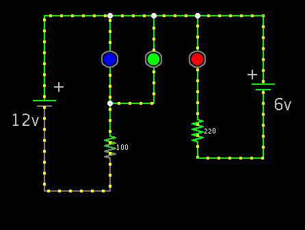
Ok, I needed a driver for a 12v led and did this: **broken link removed**
(full article explaining everything: **broken link removed**)
Vcc connected to 12v and of course GND to 0v.

It works fine, but now I need the same thing but instead of driving a 12v led I need it to be 6v, but the thing is that because of design Vcc still needs to be connected to 12v.
My question is: Can I connect GND to 6v so the voltage difference of the led is 6v??? (12v-6v=6v)
Also do I need to change anything on the circuit??

Thanks!
 

An LED sets its own voltage. The circuit sets its current.
A 6V LED will have the same current in that circuit as a 12V LED but the Mosfet will get hot and will need a heatsink since it will have 6V across it.
 

It works fine, but now I need the same thing but instead of driving a 12v led I need it to be 6v, but the thing is that because of design Vcc still needs to be connected to 12v.
My question is: Can I connect GND to 6v so the voltage difference of the led is 6v??? (12v-6v=6v)
Also do I need to change anything on the circuit??

Hi Pancra85
I've a better suggestion . you mentioned your required voltage is around 6 volts and it is supposed to be supplied form the inlet of 12 volt . ok , if you use an LM2576 which is kind of buck regulator ( switch mode ) it will deliver very high efficiency and no heat sink would be required . and you can limit the current without any loss if you refer to the on/off pin of it . ( hiccup current limiter can be achieved with it )

Best Wishes
Goldsmith
 

Ok, the led is this one: https://www.alibaba.com/product-gs/712130845/10_Watt_RGB_LED_high_power.html
it is a high power RGB and as you can see on the table you need around 12v for BLUE and GREEN but you need around 6v for RED, and also the leds have a common positive pin.
As this is the case, I need to connect 12v on the positive side, and I was thinking that I could connect 6v on the negative side of RED instead of 0v so it has the required voltage.

So the schematic I referenced on the first post is a led driver and I need one for each color (RGB, so three of them)
Of course I will only have a 12v power source and I was thinking getting 6v from it with a voltage divisor (resistors) but maybe I can get that as Goldsmith said with that LM2576, the question is if it will work connecting the RED driver to Vcc->12v and GND->6v.
 

In regard to the question, it is possible to connect separate circuits at the positive polarity.

Simplified illustration:

7640359400_1367552754.png


Current flows downward through all 3 led's.

It works because the 12V loop does not share any current flow with the 6V loop.

You can also use resistive drop to limit current through the red led. However it will waste a few watts as heat.

A buck converter is a feasible alternative, although it is more expensive and requires more work.
 

Using a 6V regulator would need to be adjusted to 4V to meet the part variation for Red 6~8V

Each part is rated to 350 per pin for RGB and thus 1050 mA total.
The fixed resistor range for a 4~6V drop becomes 11.6R~17.4R


This is possible but ... not very handy for select on test.

Unfortunately you need either a CC-sink, open-drain, PWM in linear or Buck mode regulator with 3 outputs. TI and others integrate many other features which raises cost in the above.

What's your budget?

Tony stewart
 

The LEDs are NOT powered from 6V and 12V. They need a current-limiting circuit like all LEDs do.
Their voltage and current ratings are when the ambient is 25 degrees C but they do not show how to cool them.
Their absolute maximum allowed current is 350mA if you can cool them properly.

Hee, hee. You must order a MINIMUM quantity of 500 LEDs.
 

In regard to the question, it is possible to connect separate circuits at the positive polarity.
WOW! I think that is exactly how I need to do it.

Using a 6V regulator would need to be adjusted to 4V to meet the part variation for Red 6~8V
Sorry, I don't understand why the need to adjust it to 4v.
I was thinking in connecting it like BradtheRad said and getting 6 to 8v from maybe a regulator like this one: https://schematic-audio.blogspot.com.ar/2011/10/dc-converter-using-7808-regulator-ic.html
Is that what you are all refering as "Buck mode regulator"?
 

My schematic is oversimplified of course. Where I put resistors, you will substitute your drivers and/or current regulators.

In fact the blue led should have its own regulator, and the green led likewise. That's if your 12V supply varies by a few volts. You need to prevent one led from 'hogging' current away from the other led.

However if your 12V is stable, then you might experiment with 3 resistors, and find the right combination of values that will limit current to safe levels in all 3 led's. Then one driver could control all 3 at the same time. I don't know if that was your intention.

Yes, I know it's simplified. The thing is that I need to control each led's color intensity separatedly, so I will need 3 drivers for each led anyway.

On another forum (Arduino) someone proposed to separate the common anode from the three colors and that solves a problem, now if I have 3 drivers and the one for red also has a 7806 voltage converter it works!! I tested everything.

Thanks you all! I guess I have everything covered now!
 

With 10W dissipation and a desire to keep the junction temp. something like 75'C or 50'C above room temp this translates into 50/10 or 5 deg/Watt thermal resistance for Rtot= Rjc + Rca for junction to case to ambient.Since the Rjc is often high such as 5'C/W you need a really low Rca heatsink parameter to keep it cool.

Cooling might look like a (small old) CPU heatsink. (without a fan)

Another way of specifying what audioguru said on thermal runaway, is that you can avoid this if diode Shockley Effect [V/'C] * thermal resistance ['C/W] = NTC voltage drift ['V/W] is less than the voltage drop in your current limiting resistor ( my formula)
 
Last edited:

The voltage across an LED drops as it heats which increases the current which increases the heating which increases the current which increases the heating which increases the current which increases the heating.....
This is Thermal Runaway and the LEDs will probably be destroyed unless you limit their current.
If you use a low current (for low heating) or a huge heatsink for the LEDs so they do not get hot then they might survive.
 

Status
Not open for further replies.

Similar threads

Part and Inventory Search

Welcome to EDABoard.com

Sponsor

Back
Top