frodonet
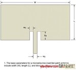
Member level 2
Hi All,
I'm currently have designed a UWB antenna where UWB stands for (ultra wide band). The problem is that my simulation for VSWR and Gain doesn't tally with the desired results.
Frequency range = 3 - 11.6Ghz
The antenna i'm designing is currently based on a research paper and I have done hundreds simulations using HFSS 11 and i do not get the desired results.
Antenna Desired Properties :
'The measured resultshows that the proposed antenna achieves an impedance bandwidth ranging from 2.9 to over 11.6 GHz and a notched band of 5.0 –5.9 GHz.'
I have also attached my HFSS file designed in HFSS 11 in this thread and it's can be seen below.
Below is my desired VSWR

Below is my desired Gain

Below are my simulated results (solution freq = 11.6Ghz)

Below are my simulated gain (Theta =0, Phi =90degrees)

My problem is that I do not get as the desired results...I have set my excitation to lumped port (and tried wave port as well) just that i don't get as close as the desired results.
I followed the HFSS guidance about the 5*w and 4*h for the excitation port but i still do not get the desired results.
I just don't understand where did i went wrong. All the dimension and design are correct and I have run the simulation about 100 times already and still not successful.
Can someone help me on this?
I'm currently have designed a UWB antenna where UWB stands for (ultra wide band). The problem is that my simulation for VSWR and Gain doesn't tally with the desired results.
Frequency range = 3 - 11.6Ghz
The antenna i'm designing is currently based on a research paper and I have done hundreds simulations using HFSS 11 and i do not get the desired results.
Antenna Desired Properties :
'The measured resultshows that the proposed antenna achieves an impedance bandwidth ranging from 2.9 to over 11.6 GHz and a notched band of 5.0 –5.9 GHz.'
I have also attached my HFSS file designed in HFSS 11 in this thread and it's can be seen below.
Below is my desired VSWR
Below is my desired Gain
Below are my simulated results (solution freq = 11.6Ghz)
Below are my simulated gain (Theta =0, Phi =90degrees)
My problem is that I do not get as the desired results...I have set my excitation to lumped port (and tried wave port as well) just that i don't get as close as the desired results.
I followed the HFSS guidance about the 5*w and 4*h for the excitation port but i still do not get the desired results.
I just don't understand where did i went wrong. All the dimension and design are correct and I have run the simulation about 100 times already and still not successful.
Can someone help me on this?
Attachments
Last edited: