Continue to Site

Welcome to EDAboard.com

Welcome to our site! EDAboard.com is an international Electronics Discussion Forum focused on EDA software, circuits, schematics, books, theory, papers, asic, pld, 8051, DSP, Network, RF, Analog Design, PCB, Service Manuals... and a whole lot more! To participate you need to register. Registration is free. Click here to register now.

help needed with Soil moisture sensor

Status
Not open for further replies.

huzeeigat

Member level 4
Joined
Mar 18, 2012
Messages
75
Helped
3
Reputation
6
Reaction score
2
Trophy points
1,288
Location
Andheri
Activity points
1,776
hello,
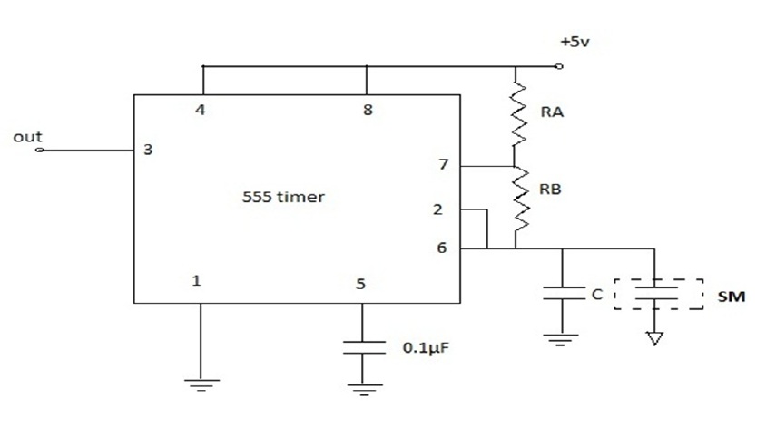
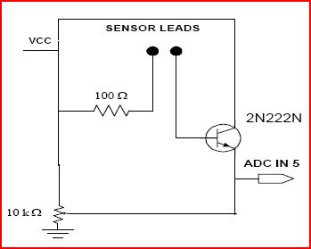
I have made a soil sensor using the circuit shown in the image...
i am stuck...coz wen i put the probes in dry soil...i get a voltage of around 0.53v after setting the 10k pot...but after adding water the o/p voltage drops to 0.02v...whereas i should get a voltage of around 4.2v..please help...
29_1334076787.jpg
 

I don't understand your circuit. Points to look at :- 1. the probes must be made of the same material or it will react to the acidity/alkalinity of the soil. 2. the probes will present a high resistance circuit. 3. Using DC on the probes will result in polarisation, all professional kit uses AC to power the probes. 4. have you wired it up correctly?
Frank
 

The probes are made of steel rods.. can you provide me with some solution..
 

Resistive moisture sensors are crude compared to dielectric sensors @ 1MHz or 80MHz. YOu can get voltage error from soil dielectric with battery effect.
Both design and schematic is wrong. Check again. 4.2V is possible remove Pot lead from Vcc and increase 100Ω to 1KΩ or more as current design tends to short out Vcc or conduct too much current = hFE * base current (hFE ~100) Then 10KΩ on emitter draws current when soil is wet and emitter pulls up to Vcc- Vsat or 4.2V for Vcc=5V.

Emitter follower buffers the probe current by hFE value. To get 4.2V across 10KΩ emitter is drawing 0.4 mA and thus base current approx 100x smaller or 4µA which translates to a soil resistance of 4V/4µA = 1MΩ. Sensor length and contact area , soil content of salts and moisture may need adjustment.
Its crude with many false readings. So Capacitance sensor is better.
 
Can you provide me with a schematic of capacitance sensor..which is working..?
 

I dont have one handy. One way is measure leakage of RF signal across soil with diode peak detector using hex Schmitt inverter chip to make clock, and detect signal on diode peak detector into schmitt inverter http://search.digikey.com/us/en/products/SN74LVC14ADR/296-1699-1-ND/405001
to make one clock... high R feedback and small Cap input to ground .. can you figure it out.


I found this circuit..frm internet is it ok?

---------- Post added at 23:45 ---------- Previous post was at 23:43 ----------

I dnt knw the relationship betn Ra and Rb..
and wer do i connect the other terminal of soil sensor..?
 

This timer will output a Logic level clock that reduces in frequency when capacitance is added. Generally in audio range, not MHz Range, DC sensitive unless R pullup is << 10KΩ. So it would work like a reverse Tach .. moisture to Hz convertor... yes
Not the best.
What do you need for output?
 

what if i connect the o/p to the interrupt of a microcontroller..? or if i connect it to a led will it keep on blinking?
 

I also have a question in the above circuit..i cant get where is the other terminal of the soil moisture sensor connected to? I mean the 1st one is connected to terminal 6 and what about the other terminal....?
 

The 555 timer specs will tell you how it works. THe Cap is charged to a threshold in an oscillator condition with a current source regulated by a reference voltage, internal current pump, external resistance and capacitance. Cm is the external cap in this case connected to ground. You need stainless steel or nickel plated probes.
First make a list of specs of what you want this circuit to do and not to do, be specific in numbers and think details

Consider;
Where is this intended to be used?
How long must it work for?
What is your budget for cost? and time?
What is the purpose of the sensor? details? cheap self powered soil sensor? portable measurement tool?

input possibilities, resistance range vs conditions, like depth of soil to be measured. range of conditions
Outputs? Human interface? Autonomous? Servo control system? hydroponic sensor?
Processing required of sensor. tools avail. power avail?
Static and high voltage protection circuit needed !!!

There are infinite number of solutions
But all depends on what you want, need and are capable of doing.

Fastest way to learn is reverse engineer;
the state of the art commercially,
or patents,
or consumer products,

Then make it work and try to understand it and possibly improve it for your needs.

To make an AC sensor, here using capacitance of the dielectric, which is water embedded in soil, you begin realize it is not ideal and has lossy and galvanic characteristics.
It also changes with depth. So the probe should be insulated and only the end exposed for a certain length so you can measure at desired depths independent of surface watering. Some products use chalk or gypson coated probes to absorb moisture, which works but adds delay time, which is why RF Cap method is better.

If you decide to measure C@f, determine why higher f is better for some conditions, but if you only want cheap and dirty then use DC resistance and expect unreliable results.
If you choose %moistiure to C to F conversion then convert F to % moisture using an F to V converter (eg. tach circuit with pulse charge open switch to diode cap)

I suggest you make a list of the specs for yourself before you start to design ANYTHING. Understand what you need , nice to have and do not want and specify it. Otherwise, you will spin your wheels. like this thread.

Once you go thru this process in detail, the solution looks simple and elegant, but the process to get there is not. That is what design is all about.

That concludes my sermon :lol:
 
Last edited:

Resistive moisture sensors are crude compared to dielectric sensors @ 1MHz or 80MHz. YOu can get voltage error from soil dielectric with battery effect.
Both design and schematic is wrong. Check again. 4.2V is possible remove Pot lead from Vcc and increase 100Ω to 1KΩ or more as current design tends to short out Vcc or conduct too much current = hFE * base current (hFE ~100) Then 10KΩ on emitter draws current when soil is wet and emitter pulls up to Vcc- Vsat or 4.2V for Vcc=5V.

Emitter follower buffers the probe current by hFE value. To get 4.2V across 10KΩ emitter is drawing 0.4 mA and thus base current approx 100x smaller or 4µA which translates to a soil resistance of 4V/4µA = 1MΩ. Sensor length and contact area , soil content of salts and moisture may need adjustment.
Its crude with many false readings. So Capacitance sensor is better.

Could you please post the correct Resistive moisture sensor diagram?
 

There was a project that detects when soil becomes dry but it didn't work so I fixed it. I built many of them.
1) It uses an AC signal at the stainless steel probes.
2) When the soil was damp the LED was turned off so its two AAA alkaline cells battery lasted for months.
3) When the soil dried a little then the LED dimly blinked.
4) When the soil was very dry the LED blinked brightly.

I removed the parts that blinked the LED and I filtered its pulse-width-modulated output into DC and somebody said it gives a good DC output:
 

Attachments

  • Moisture monitor-2.PNG
    Moisture monitor-2.PNG
    15.1 KB · Views: 177

Status
Not open for further replies.

Part and Inventory Search

Welcome to EDABoard.com

Sponsor

Back
Top